Single Busbar with Bus section Configuration
Single Busbar with Bus section Configuration & Operation
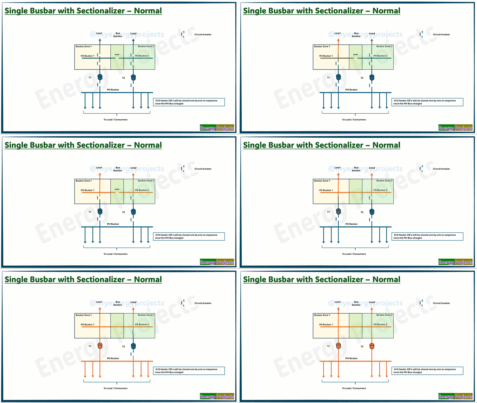
First, we look at the very simple representation of this busbar configuration.
Line 1 is charged from the remote substation by closing the remote circuit breaker. Once energized, the main circuit breaker is closed to charge HV Bus 1. Similarly, Line 2 is charged, and HV Bus 2 is energized. After both buses are live, the bus section breaker is closed to interconnect them.
Now, the HV bus is energized by two incoming line feeders. To supply power to the MV outgoing feeder, the transformer HV breaker is closed, charging the transformer on the HV side. Closing the MV breaker then charges the MV bus, delivering power to consumers.
On the right-hand side, Transformer 2 is also charged in the same way to share the load and prevent overloading.
The complete substation operates ideally without any busbar faults.
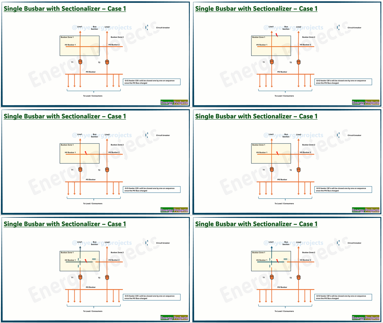
Fault case study - Case 1
A fault occurs in protected Zone 1. The busbar protection relay detects it and sends a trip command to all breakers connected to HV Bus 1, including the bus section breaker. It also issues a trip command to the Line 1 remote substation breaker to isolate the entire Incomer 1 from HV Bus 1.
As a result, power from Line 1 is interrupted, and the fault is isolated from the grid. However, MV power supply continues uninterrupted through Line 2 and Transformer 2.
Advantages:
Simple design with one bus section
Easy operation and maintenance
Less space required
Improved reliability
Reduced outage time
Better protection coordination
Disadvantages:
Limited flexibility
Higher cost than single busbar
More space than single busbar
Still lacks full reliability
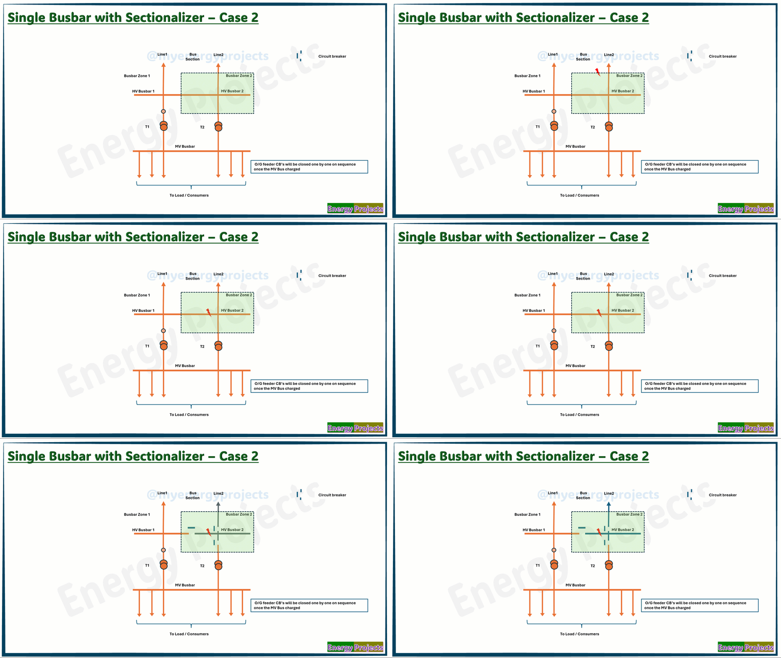
Fault case study - Case 2
A fault occurs in protected Zone 2. The busbar protection relay detects it and sends a trip command to all breakers connected to HV Bus 2, including the bus section breaker. It also issues a trip command to the Line 2 remote substation breaker to isolate the entire Incomer 2 from HV Bus 2.
As a result, power from Line 2 is interrupted and the fault is isolated from the grid. However, MV power supply continues uninterrupted through Line 1 and Transformer 1.
Once the fault is cleared, then the same process will be followed to charge the busbar and transformer to feed the power through MV outgoing feeders as shown in first diagram.


