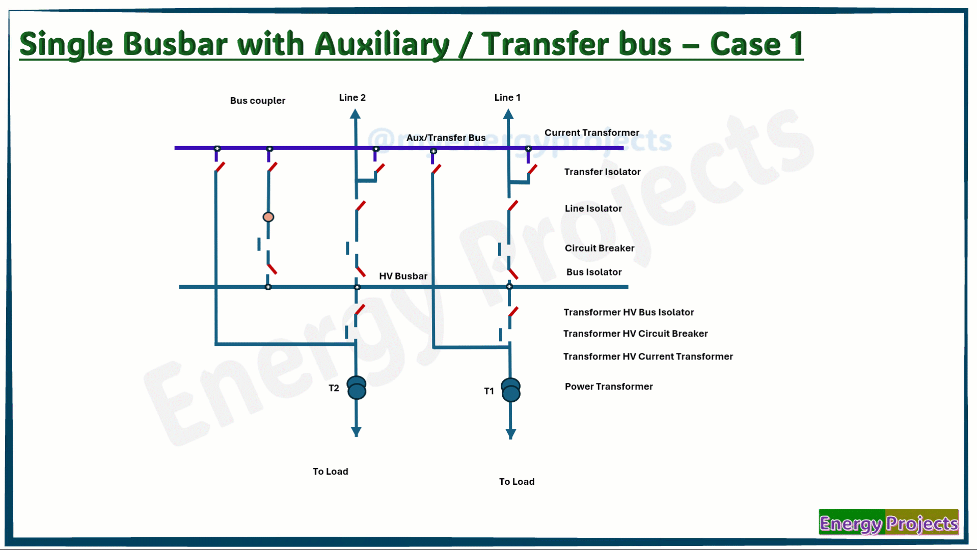
Single Busbar with Aux/Transfer Bus Configuration
Single Busbar with Bus section Configuration & Operation
First, we look at the very simple representation of this busbar configuration.
We have to close the Line Disconnector and Bus Disconnector of Line 2. Line 2 is already charged from the remote substation. After that, we need to close the Main Circuit Breaker to charge the HV Bus. Line 1 will also be charged in the same way as Line 2. The main HV bus is energized through two incomer line feeders. We need to transfer power to the load by closing the Transformer Breakers, as shown here.
The substation is operating under normal conditions without any busbar fault.
Fault case study - Case 1
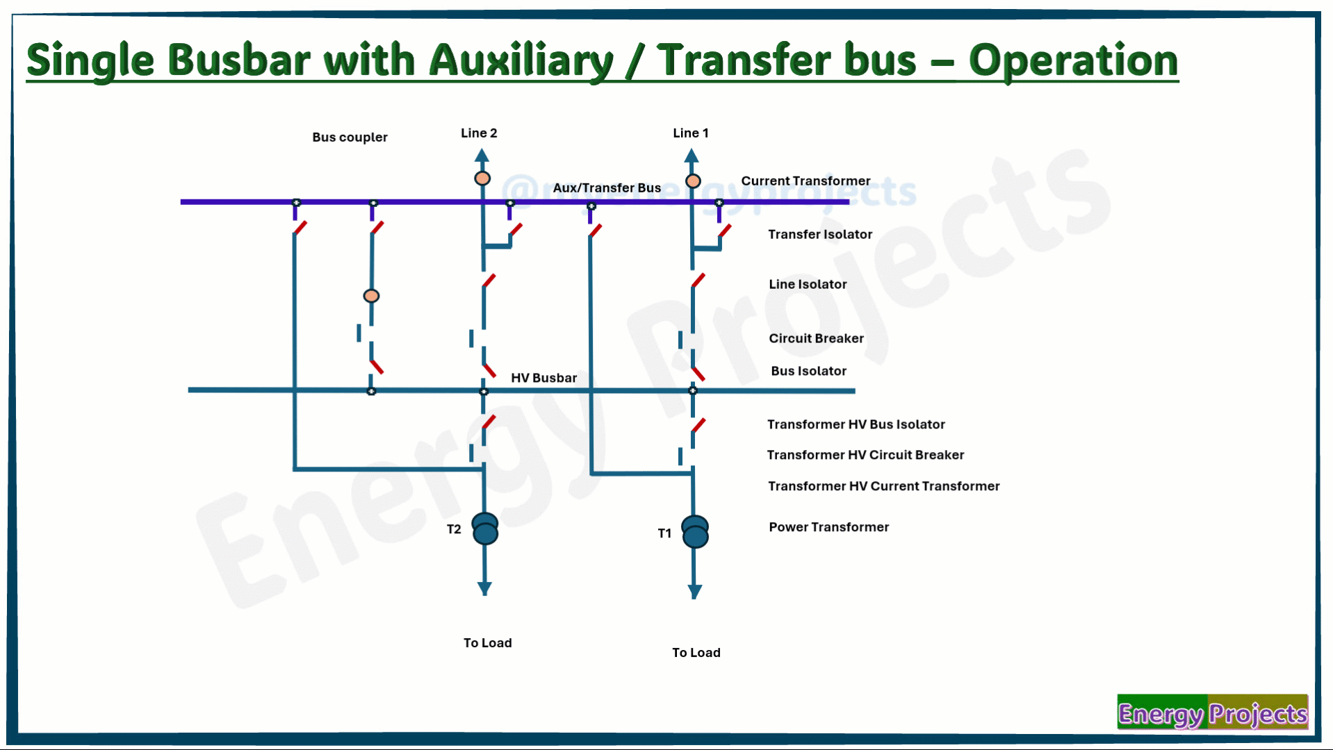
Line 2 is getting charged, similar to Case 1 study. In this case, the busbar is already charged. Line 1 has some issues with its circuit breaker or is currently under maintenance.
To feed power to the HV bus, the following procedure needs to Ensure that all transfer isolators are in the open condition. Then, close the transfer isolator of the Line feeder and the isolators in the Bus Coupler (BC).
Next, we need to charge Line 1 from the remote substation. After that, close the Bus Coupler Circuit Breaker (BC CB) to connect Line 1 to the main busbar.
Here, it is important to note that the power is routed to the main busbar through the transfer bus coupler.
The main HV bus is normally charged by two incomer line feeders. Finally, to transfer power to the load, we need to close the Transformer Breakers, as shown here.
Advantages:
Simple design
Easy operation and maintenance
Improved reliability
Reduced outage time
Disadvantages:
Limited flexibility
Higher cost than single busbar
More space than single busbar
Still lacks full reliability
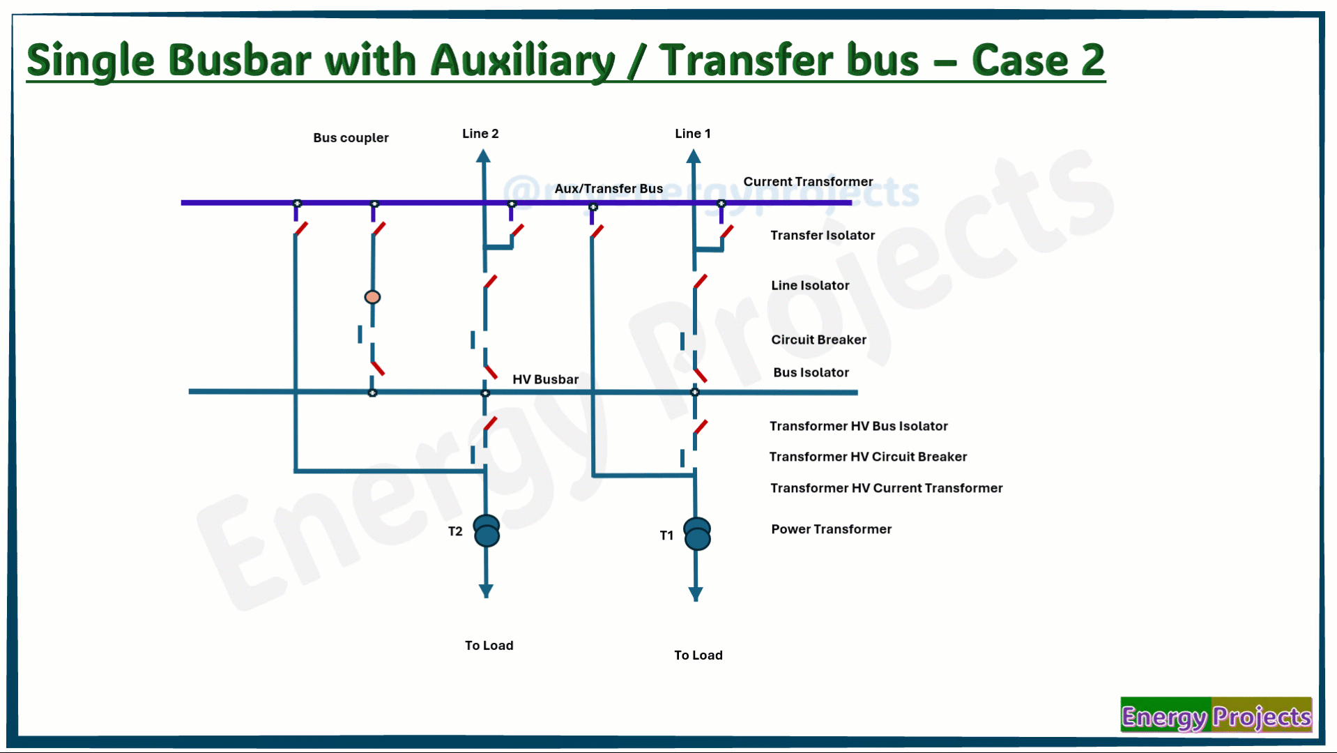
Fault case study - Case 2
Line 1 and Line 2 are being charged the same way as in normal operation. As you can see, the HV bus is now charged. Next, we need to transfer power to the load by closing the Transformer breakers, as shown here. However, Transformer 1 Circuit Breaker (CB) has an issue. So, we need to follow the same process as Ensure all transfer isolators are in the open position. Then, close the Transformer Transfer Isolator and both isolators in the Coupler. After that, close the Coupler Circuit Breaker to transfer power from the HV bus to the load. This setup allows the load to be fed through the transfer path, as shown here
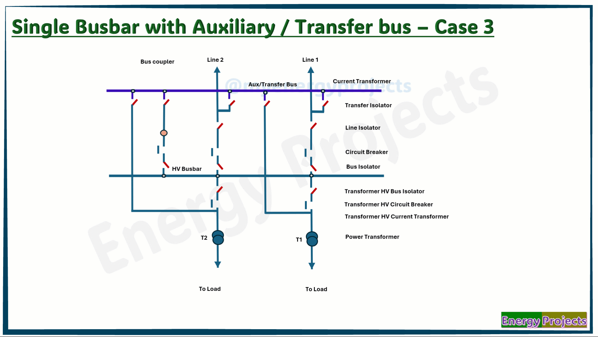
Fault case study - Case 3
In this case, the Line Feeder Circuit Breakers (CBs) are either under maintenance or facing issues. Therefore, we can use only one of the line feeders to charge the main busbar through the transfer bus coupler.
If both lines need to be charged simultaneously, it would require an additional coupler with a special busbar arrangement, which will be discussed in future scanario. To feed power to the load, we must follow a specific procedure. First, ensure all transfer isolators are in the open position. Then, close the transfer isolator of the selected feeder along with the isolators in the bus coupler.
Next, the line must be charged from the remote substation. After that, close the Bus Coupler Circuit Breaker (BC CB) to connect the line to the main busbar. As you can observe, power is routed to the main busbar through the transfer bus coupler.
Once the main HV bus is charged by the line feeder, power can be transferred to the load by closing the transformer breakers, as shown here