Single Busbar with Bus section +Transfer bus coupler + Section Isolator configuration
Single Busbar with Transfer bus + with Transfer Section isolator configuration
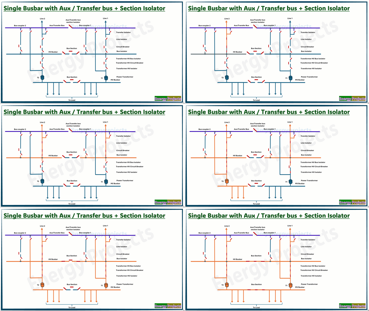
First, we look at the very simple representation of this busbar configuration, Here You can see the main busbar split into two sections with a bus section isolator, as well as a transfer busbar split with a section isolator.
Operation
First, we will close the line isolator and bus isolators. We begin by charging Line 2 from a remote substation by closing the remote substation circuit breaker. Once Line 2 is charged, we close the Line circuit breaker to charge the HV bus. Similarly, Line 1 will be charged in the same manner as Line 2.
The main HV bus is powered through two incoming line feeders. After that, we transfer power to the load by closing the transformer bay isolators and breakers. If either line is overloaded or in various work scenarios, we can close the bus section, as seen here.
The complete substation operates ideally without any busbar faults.
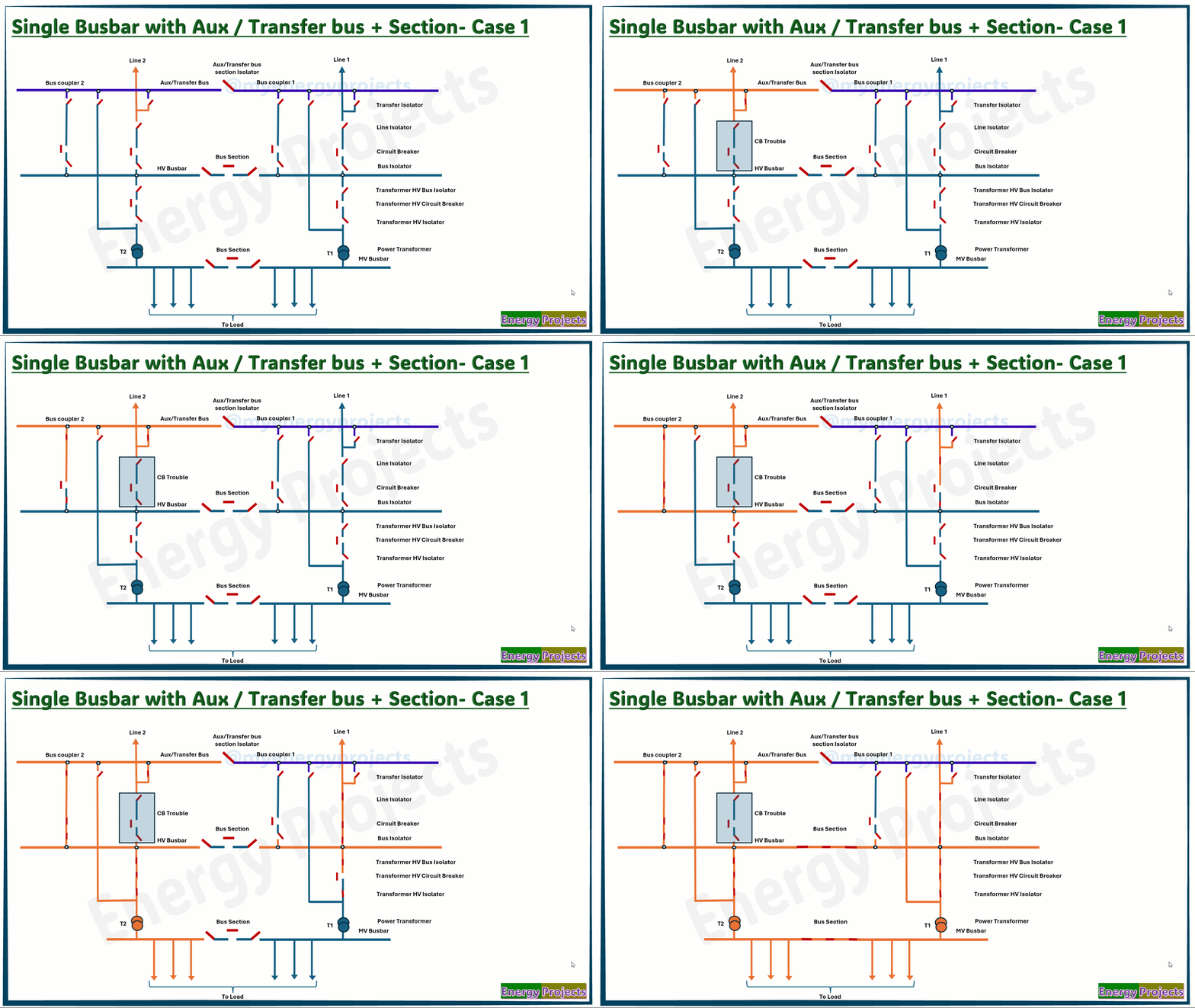
Fault case study - Case 1
Line 2 will be charged . However, if the Line 2 breaker is experiencing trouble or is under maintenance, we need to transfer power to the main bus through the transfer bus coupler. To ensure safe operation, we first need to check that all transfer isolators are open. Then, we close the transfer isolator for Line 2 and close both disconnectors of Bus Coupler 2. Afterward, we close the BC circuit breaker (CB) to connect the line to the main busbar.
At this point, power is routed to the main busbar through the transfer bus coupler. Once the HV bus is charged, Line 1 will be charged as described earlier.
Next, we follow the same procedure to charge the MV outgoing feeders.
The same method should be applied if the Line 1 CB is having trouble or is under maintenance.
Advantages:
Improved reliability
Reduced outage time
Better protection coordination
Disadvantages:
Limited flexibility
Higher cost than single busbar
More space than single busbar
Still lacks full reliability
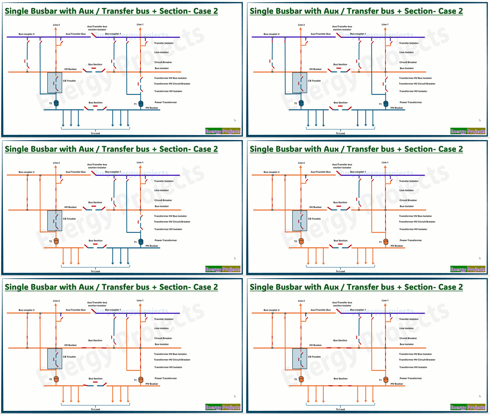
Fault case study - Case 2
Line 2 and Line 1 will be charged as in Case 1, as shown here. If Transformer 2 breaker is experiencing trouble or is under maintenance, we need to transfer power from the main bus to the load through the transfer bus coupler. To ensure safe operation, we first check that all transfer isolators are open. Then, we close the transfer isolator for Transformer 2 and close both disconnectors of Bus Coupler 2. Afterward, we close the BC circuit breaker (CB) to connect the transformer to the MV bus and the load.
Next, we charge Transformer 1 to connect it to the MV outgoing feeders by closing its isolators and breaker.
The same method should be followed if Transformer 1 CB is having trouble or is under maintenance.
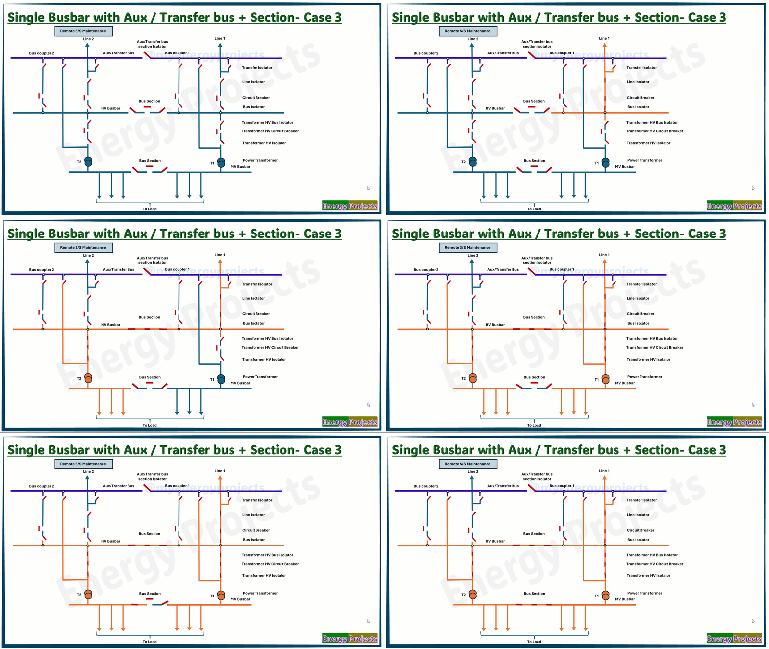
Fault case study - Case 3
In this case, if Line 2 and the remote substation are under maintenance, Line 1 will be charged the same way as in Case 1 to charge the HV bus. We will also close the bus section to charge Busbar 2.
Now, with the entire bus charged, we follow the same procedure to charge the transformers and close their breakers to feed power to the load.
The same method should be followed if the remote Line 1 is under maintenance.
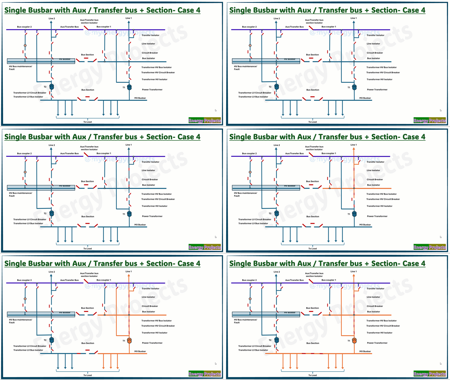
Fault case study - Case 4
In this case, if Busbar 2 is under maintenance or undergoing fault repair works, we need to charge Line 1 and the transformers by closing their breakers to supply power. After that, we close the MV section breaker to feed the remaining MV outgoing feeders.
The same procedure should be followed if the remote Busbar 1 is under maintenance
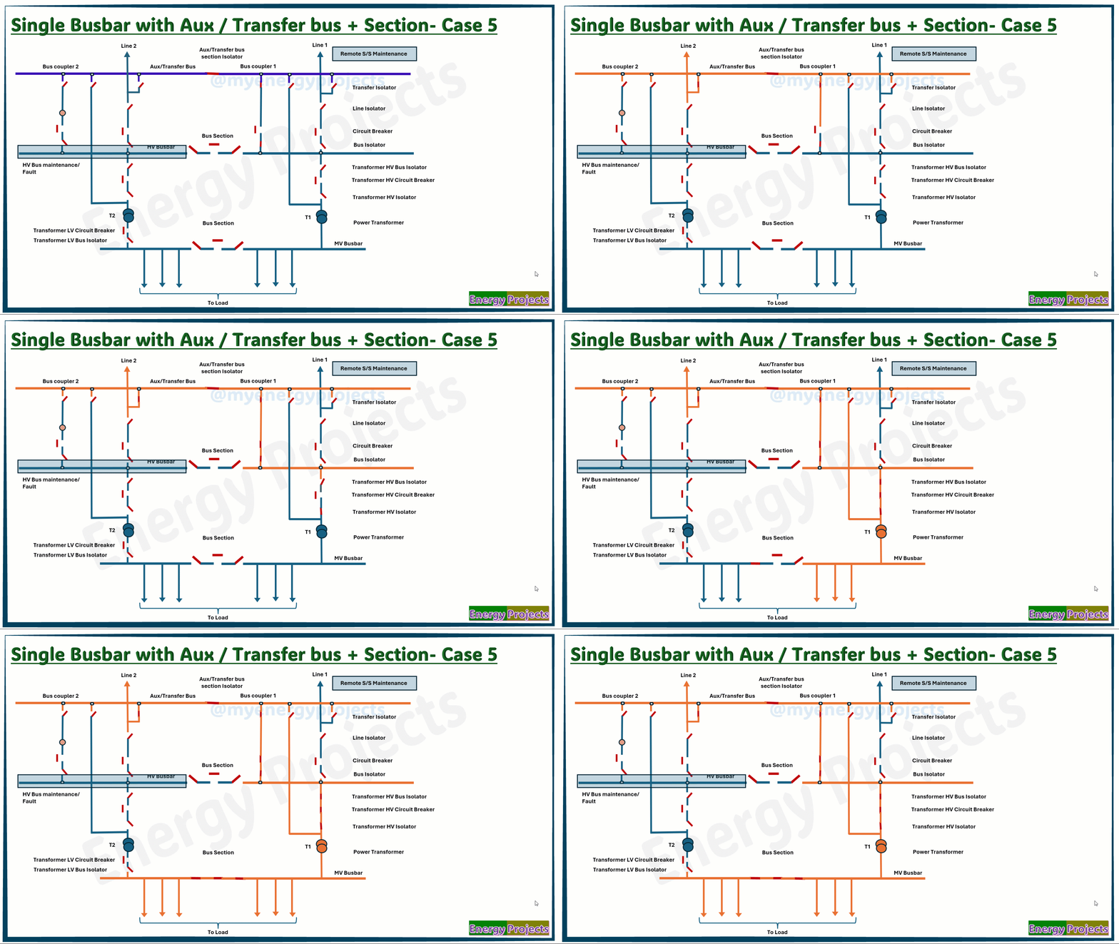
Fault case study - Case 5
In this case, with Busbar 2 and Line 1, remote substation under maintenance, we need to transfer power from Line 2 to the load through the transfer bus coupler. To ensure safe operation, we must first check that all transfer isolators are open, then close the Line 2 transfer isolator. Next, we close the section isolator of the transfer bus and both isolators of the transfer bus coupler 1. We then charge Line 2 remotely and close the coupler 1 circuit breaker to charge Busbar 1. Afterward, we close the transformer circuit breaker and the MV bus section to charge all outgoing feeders.
The same procedure should be followed if Busbar 1 and Line 2, remote substation are under maintenance.
