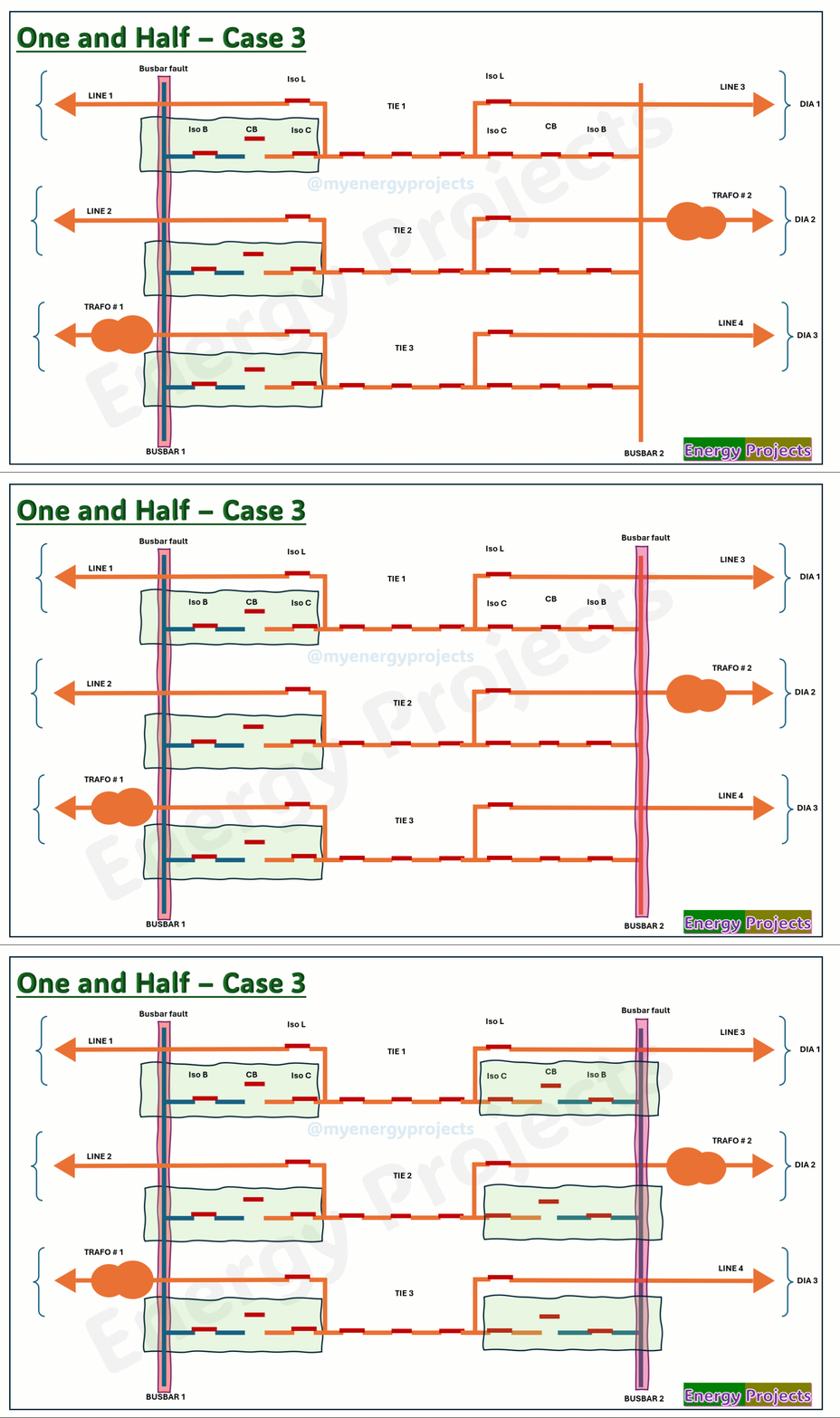
One and half Breaker configuration
One and half Breaker Configuration
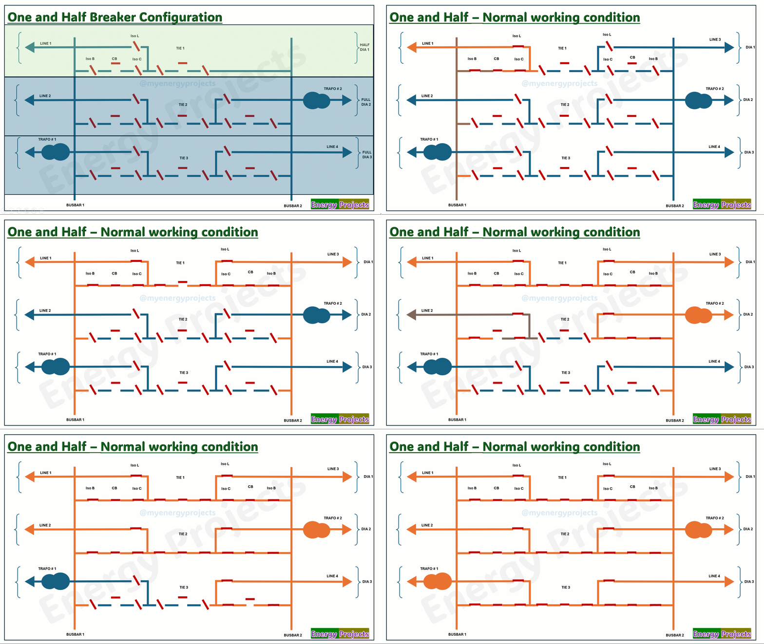
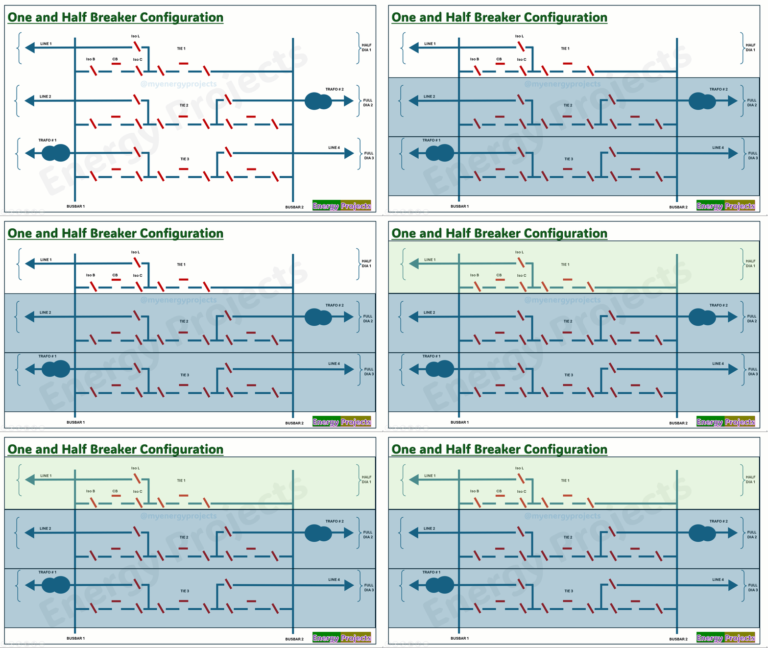
First, we look at the very simple representation of busbar configuration.
You can see Busbar 1 and Busbar 2, which are connected to lines and transformers through circuit breakers. The term "one and a half" is derived from the fact that two bays are controlled by three breakers. Therefore, it is called the one and a half breaker scheme.
Here, I would like to explain about the Dia. The Dia contains two bays, which can either be lines on both sides of the buses or a combination of a line and a transformer feeder.
The connection between Busbar 1 and Busbar 2 through the middle breaker is called the Tie. When both bays are present, the setup is called a full Dia.
In some cases, the Dia contains only one bay, with the Tie breaker directly connected to the busbar. This is called a half Dia.
Advantages:
Higher reliable
Higher flexible
Less outage time
Very supportive for Protection coordination
Dis Advantages:
Complex Design
Very Higher cost
Very Higher space
Higher maintenance
Critical Troubleshooting
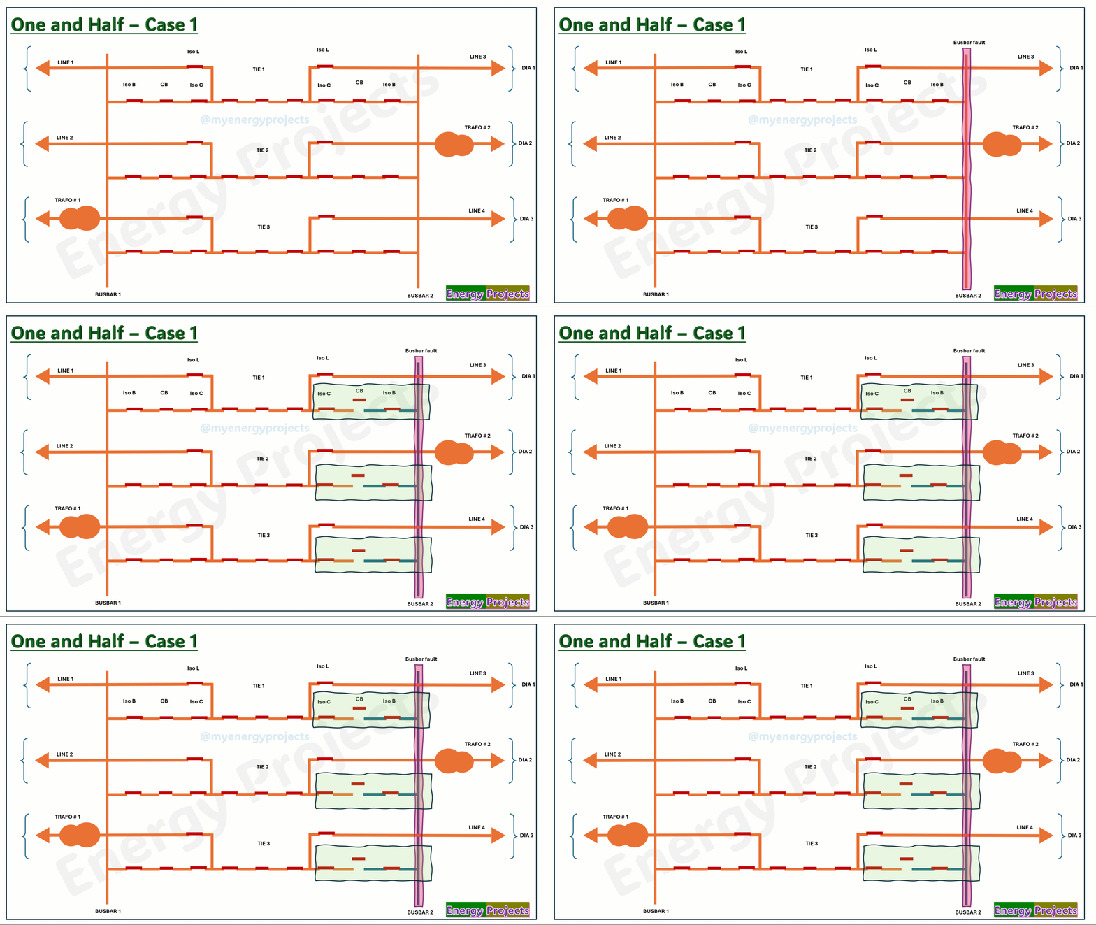
Fault case study - Case 1
In the event of a fault on Busbar 2, all circuit breakers connected to Busbar 2 will trip to isolate the fault.
However, power supply is maintained through the feeders connected to Busbar 1, via the TIE breakers, ensuring continuity of service.
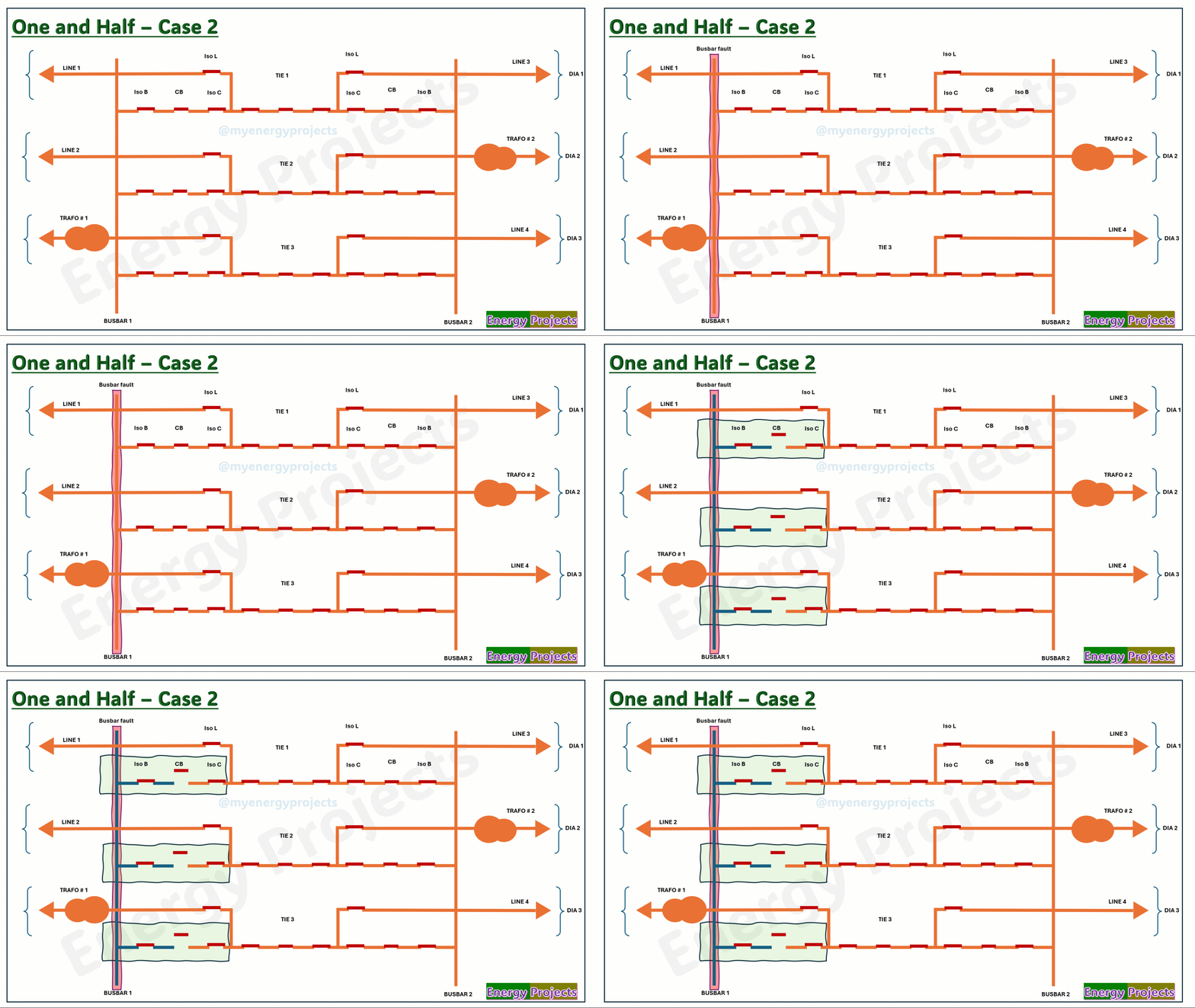
Fault case study - Case 2
In the event of a fault on Busbar 1, all circuit breakers connected to Busbar 1 will trip to isolate the fault.
However, power is retained through the feeders connected to Busbar 2, via the TIE breakers, ensuring uninterrupted power supply
Fault case study - Case 3
In the event of a fault on both Busbar 1 and Busbar 2, all circuit breakers connected to both busbars will trip to isolate the fault. However, power can still be retained through the lines connected to transformers, using the TIE breakers as a backup path.
This type of operation is very rare and typically performed only under exceptional conditions.
Operation
In this case, all the bay isolators of Line 1 will be closed, and Line 1 will be charged. Once the line is charged, we can close the circuit breaker to energize HV Busbar 1.
Similarly, we can charge Line 3 to supply power to Busbar 2. Once both Line 1 and Line 3 are charged, we can close the TIE 1 breaker. As soon as both busbars are energized, we can charge Transformer 3 by closing all its bay isolators and the associated circuit breaker. Line 2 will be charged in the same manner, followed by closing the TIE 2 breaker. Then, Line 4 and Transformer 2 will be charged, and the TIE 3 circuit breaker will be closed.
At this point, all feeders are energized and in proper working condition.
