01.Hair Pin Type
Single Busbar Configuration
Single Busbar with Bus section Configuration
Single Busbar with Transfer busbar configuration
Single Busbar with Bus section + Transfer bus coupler + Section Isolator configuration
Double Busbar with Bus coupler Configuration
Double Busbar with Bus coupler + Bypass Isolator Configuration
Double Busbar with Bus coupler + Transfer Buscoupler configuration
One and Half Breaker Busbar Configuration
Busbar Configuration
Track Sequence of Engineering
Advantages of Dead Tank Current Transformer
Enhanced Safety
The tank is grounded, reducing the risk of electric shock during maintenance and inspection.
Multiple Secondary Cores
Easily accommodates multiple cores for protection, metering, and control functions in one unit.
High Reliability
Suitable for outdoor and high-voltage environments with a rugged, sealed design that withstands harsh weather.
Ease of Maintenance
Since the tank is at ground potential, it is safer and easier to perform routine checks or repairs.
Better Insulation and Cooling
Uses oil or SF₆ gas as an insulating and cooling medium, which provides effective thermal management.
Stable Mechanical Design
The grounded tank structure provides solid mechanical support and minimizes vibration and movement under short-circuit conditions.
Suited for High Voltage Applications
Commonly used in 66 kV, 132 kV, 220 kV, and even up to 765 kV substations.
Disadvantages of Dead Tank Current Transformer
Larger and Heavier
The construction is bulkier and heavier compared to live tank CTs, making transport and installation more difficult.
More Expensive
Due to its size, insulation system, and multi-core capability, dead tank CTs are generally more costly.
Oil or Gas Handling Required
Needs careful handling of insulating medium (oil or SF₆), including monitoring for leaks, moisture, and pressure levels.
Environmental Concerns
Use of SF₆ gas (a potent greenhouse gas) poses environmental risks if not properly handled or sealed.
Installation Space Requirement
Requires more space in substations compared to live tank versions due to its size.
Complex Design
The internal structure is more complex, which may increase the time and cost for diagnostics and repairs.
Dead Tank Current Transformer (CT)
It is a special type of instrument transformer used in high-voltage electrical systems to safely measure large currents and supply proportional signals to measuring instruments, protective relays, and control systems. These transformers are essential for the monitoring, control, and protection of power systems.
Why It's Called a "Dead Tank"
In a dead tank CT, the main body or tank of the transformer is grounded, meaning it does not carry high voltage. The live high-voltage conductor passes through an insulated bushing inside the grounded tank, which houses the core and secondary windings. This is in contrast to a live tank CT, where the tank is energized & Where the real core of the secondary terminals will be accommodated
Construction and Design
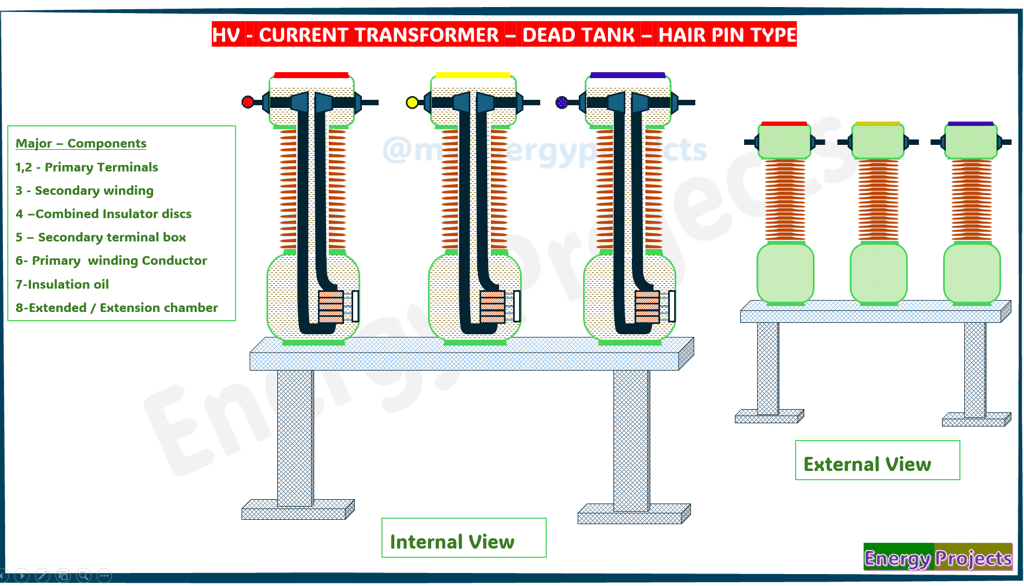
A dead tank - hair pin type looks like that shape, and CT is designed with the following key components:
1, 2 – Primary Terminals
Primary terminals are the external points where the high-voltage transmission line connects to the CT. These terminals allow the line current to enter and exit the transformer. They are robust and designed to withstand high voltage and mechanical stress. Located at the top of the CT, they are usually made of aluminum or copper alloys. Their design ensures secure electrical contact with minimal resistance.
3 – Secondary Winding
The secondary winding is housed within the CT and is responsible for converting high primary current into a standardized, lower value, typically 1A or 5A. This scaled-down current is then used for metering, protection, and monitoring systems. The winding is carefully insulated and precision-wound to ensure accuracy. It is magnetically linked to the primary conductor through a laminated core. Any deviation in its output can affect system readings.
4 – Combined Insulator Discs
These insulator discs provide both mechanical support and high-voltage electrical insulation between the energized parts and grounded tank. They are generally made of porcelain or polymer and designed to withstand environmental stresses like rain, dust, and temperature variations. The combined function helps reduce size and material costs. Their robust construction also resists external mechanical forces such as wind and seismic loads.
Working Principle
The dead tank CT works on the principle of electromagnetic induction. When current flows through the primary conductor, it creates a magnetic field. This magnetic field induces a current in the secondary winding, which is proportional to the primary current based on the turn ratio of the transformer. The reduced current in the secondary winding can then be safely used for measurement or protection.
5 – Secondary Terminal Box
This is an enclosure mounted on the CT body that houses the terminals of the secondary winding. It allows safe and organized connection of control cables going to meters, protection relays, and SCADA systems. Often weatherproof, the box may also include grounding terminals, shorting links, and cable glands. This component ensures safe handling and secure operation during maintenance. Some designs include heaters to prevent condensation inside.
6 – Primary Winding Conductor
The primary winding usually consists of a single solid conductor that passes through the magnetic core of the CT. Since it carries the full current of the transmission line, it is designed with high mechanical and thermal strength. It is insulated to withstand the line voltage and is often supported rigidly within the CT tank. Despite its simplicity, it plays a crucial role in establishing the magnetic field for transformation.
7 – Insulation Oil
Insulating oil is filled inside the CT tank to provide dielectric insulation and remove heat from internal components. It surrounds the windings and core, helping prevent electrical breakdown by enhancing insulation strength. The oil also acts as a coolant, transferring heat to the tank walls. Regular oil testing is necessary to ensure purity and performance. Contaminated oil can reduce insulation and cause internal faults.
8 – Extended / Extension Chamber
This chamber is an extension of the CT’s main tank and is designed to handle oil expansion caused by temperature changes. It may include a conservator tank or flexible diaphragm system to maintain oil volume and prevent pressure buildup. The extension also provides space for additional cores or monitoring equipment if needed. Proper sealing and a silica gel breather are used to block moisture ingress. It supports long-term reliability under outdoor conditions.