01.Over Current Protection
Overcurrent protection plays a crucial role in defending electrical systems from faults and abnormal conditions. Without it, faults can seriously damage equipment, resulting in costly repairs, long service interruptions, and safety risks for nearby personnel. To avoid these issues, having a dependable and effective protection system is essential.
Track Sequence of Engineering
Over Current Protection applies for all equipments ,
Power Transformers
Incoming / Outgoing Feeders
Busbars ( Depends on the Rating )
Capacitor Banks
Motors
Generators
Cables
Reactors
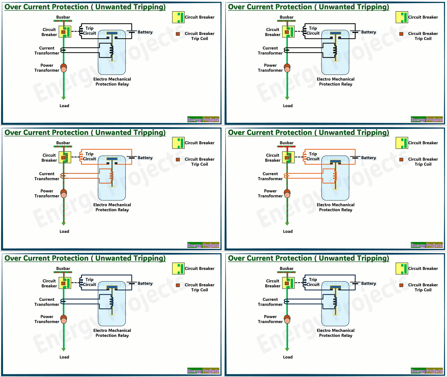
Normal Working Principle ( Un Healthy Trip)
When the current in a system exceeds a predefined limit, the protection device detects it and sends a trip signal to isolate the faulty section.
In the drawing below, we are closing the breaker to supply power. The current transformer (CT) measures the current and energizes the relay, which then sends a trip signal to the circuit breaker (CB) to disconnect the circuit.
However, you’ll notice that the relay is also tripping under normal load conditions. This happens because there is no restraining force present to prevent unnecessary operation. This kind of unwanted tripping is undesirable and must be avoided.
Types of Over Current Protection:
Non-Directional Overcurrent Protection
Directional Overcurrent Protection
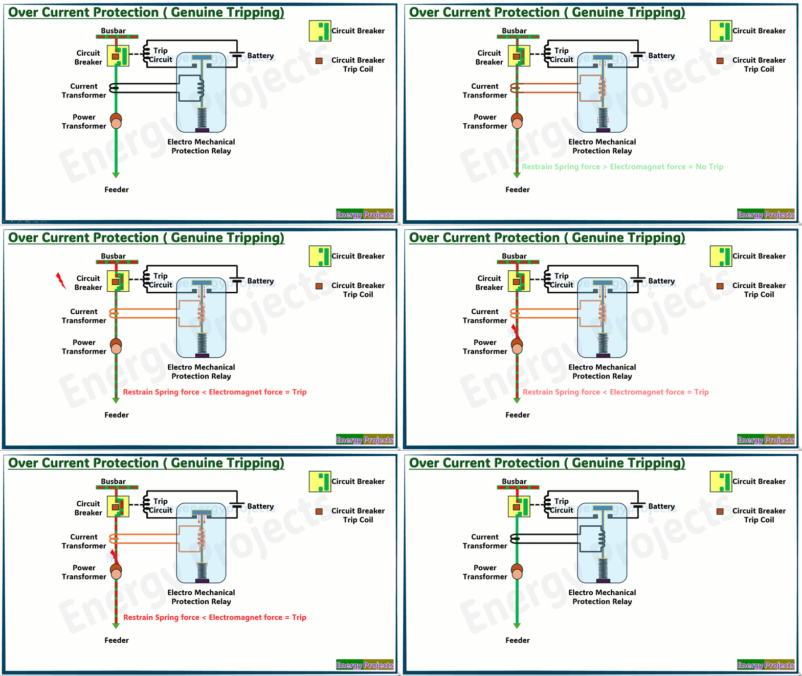
Modified Working Principle ( Genuine Trip):
If you look at the modified drawing below, the relay will not trip under normal load conditions, unless the current exceeds a preset limit. There is a restraining spring visible whcih can be adjustable in the design, which holds the relay mechanism in place under normal conditions which we set accordingly . The relay will only operate when the electromagnetic force generated by the fault current overcomes the tension of the spring, causing it to trip.
Below the representation, In the event of a fault, the resulting current energizes the electromagnet, increasing its magnetic force sufficiently to overcome the restraining spring and activate the relay mechanism. After tripping, the restraining spring resets the relay to its normal position
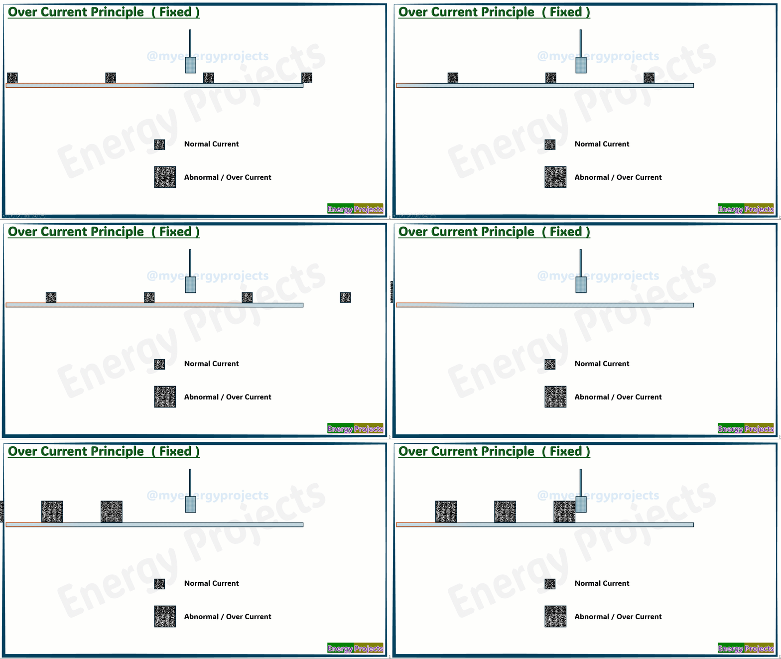
Normal Working Analogy
The small box operates within the normal size range, and its height stays within the limits is fixed. However, occasionally a larger box appears, which exceeds the allowed height. This unexpected size causes an issue with the system. When the larger box enters, it interferes with the operation and leads to the machine stopping. To ensure smooth functioning, this height variation needs to be controlled. If we want to allow the Biger.
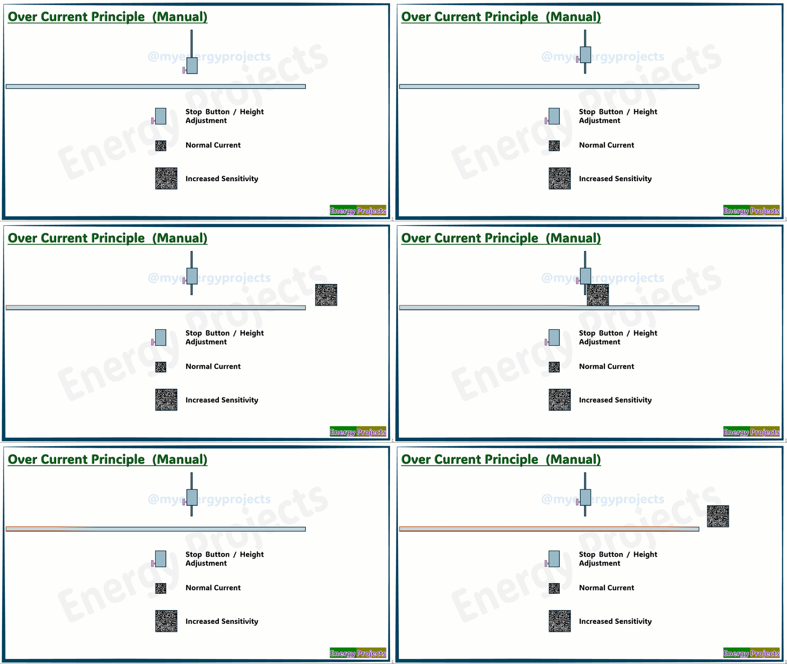
Manual Working Analogy
If we want to allow bigger size boxes, we need to increase the height settings. This adjustment will prevent the machine from stopping when larger boxes are processed. By updating the height limits, the system can handle all box sizes smoothly and without interruption.


