02.Eye Bolt Type - Current
Transformer
Track Sequence of Engineering
Advantages of Eye Bolt Type Current Transformers
1. Space-Saving Design
Eye bolt CTs are compact and lightweight, making them ideal for installations with limited space, such as control panels or indoor enclosures.
2. Economical Option
Their simple construction and materials make them more affordable compared to bulkier CT types like dead tank or live tank CTs.
3. Quick and Simple Installation
These CTs can be easily mounted around existing conductors without requiring major disassembly, especially in split-core models.
4. Low Maintenance Needs
As they don’t rely on fluids or gases for insulation, they require minimal upkeep over their lifespan.
5. Ideal for System Upgrades
Split-core eye bolt CTs can be retrofitted on live systems, reducing the need for downtime during installation or upgrades.
Disadvantages of Eye Bolt Type Current Transformers
1. Voltage Limitations
Primarily used in low to medium voltage systems (typically below 33 kV), making them unsuitable for high-voltage power networks.
2. Less Durable for Harsh Conditions
Not designed to withstand extreme environmental stress, mechanical impact, or high fault currents like more robust CT types.
3. Limited Functionality
Usually supports fewer secondary windings, which can restrict its use in systems requiring separate metering and protection outputs.
4. Sensitivity to Installation
Performance can be affected by improper positioning or alignment on the conductor, impacting measurement accuracy.
5. Lower Thermal Handling
Without cooling mediums like oil or gas, eye bolt CTs may experience thermal limitations under heavy current loads.
6. Not Suitable for High Fault Currents
These CTs are not engineered to handle the physical and thermal stress of high short-circuit currents
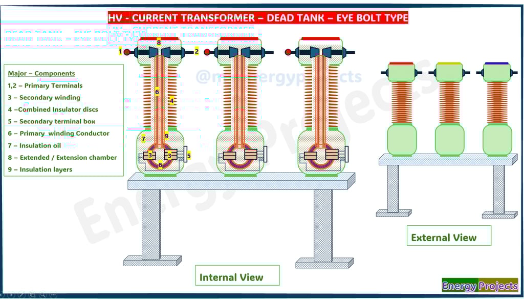
Dead Tank Current Transformer (CT)
It is a special type of instrument transformer used in high-voltage electrical systems to safely measure large currents and supply proportional signals to measuring instruments, protective relays, and control systems. These transformers are essential for the monitoring, control, and protection of power systems.
Why It's Called a "Dead Tank"
In a dead tank CT, the main body or tank of the transformer is grounded, meaning it does not carry high voltage. The live high-voltage conductor passes through an insulated bushing inside the grounded tank, which houses the core and secondary windings. This is in contrast to a live tank CT, where the tank is energized & Where the real core of the secondary terminals will be accommodated
Construction and Design
A dead tank - eye bolt type looks like that shape, and CT is designed with the following key components:
1, 2 – Primary Terminals
Primary terminals are the external points where the high-voltage transmission line connects to the CT. These terminals allow the line current to enter and exit the transformer. They are robust and designed to withstand high voltage and mechanical stress. Located at the top of the CT, they are usually made of aluminum or copper alloys. Their design ensures secure electrical contact with minimal resistance.
3 – Secondary Winding
The secondary winding is housed within the CT and is responsible for converting high primary current into a standardized, lower value, typically 1A or 5A. This scaled-down current is then used for metering, protection, and monitoring systems. The winding is carefully insulated and precision-wound to ensure accuracy. It is magnetically linked to the primary conductor through a laminated core. Any deviation in its output can affect system readings.
4 – Combined Insulator Discs
These insulator discs provide both mechanical support and high-voltage electrical insulation between the energized parts and grounded tank. They are generally made of porcelain or polymer and designed to withstand environmental stresses like rain, dust, and temperature variations. The combined function helps reduce size and material costs. Their robust construction also resists external mechanical forces such as wind and seismic loads.
Working Principle
The dead tank CT works on the principle of electromagnetic induction. When current flows through the primary conductor, it creates a magnetic field. This magnetic field induces a current in the secondary winding, which is proportional to the primary current based on the turn ratio of the transformer. The reduced current in the secondary winding can then be safely used for measurement or protection.
5 – Secondary Terminal Box
This is an enclosure mounted on the CT body that houses the terminals of the secondary winding. It allows safe and organized connection of control cables going to meters, protection relays, and SCADA systems. Often weatherproof, the box may also include grounding terminals, shorting links, and cable glands. This component ensures safe handling and secure operation during maintenance. Some designs include heaters to prevent condensation inside.
6 – Primary Winding Conductor
The primary winding usually consists of a single solid conductor that passes through the magnetic core of the CT. Since it carries the full current of the transmission line, it is designed with high mechanical and thermal strength. It is insulated to withstand the line voltage and is often supported rigidly within the CT tank. Despite its simplicity, it plays a crucial role in establishing the magnetic field for transformation.
7 – Insulation Oil
Insulating oil is filled inside the CT tank to provide dielectric insulation and remove heat from internal components. It surrounds the windings and core, helping prevent electrical breakdown by enhancing insulation strength. The oil also acts as a coolant, transferring heat to the tank walls. Regular oil testing is necessary to ensure purity and performance. Contaminated oil can reduce insulation and cause internal faults.
8 – Extended / Extension Chamber
This chamber is an extension of the CT’s main tank and is designed to handle oil expansion caused by temperature changes. It may include a conservator tank or flexible diaphragm system to maintain oil volume and prevent pressure buildup. The extension also provides space for additional cores or monitoring equipment if needed. Proper sealing and a silica gel breather are used to block moisture ingress. It supports long-term reliability under outdoor conditions.
9 – Insulation
Eye bolt type current transformers use a simple yet effective insulation system suited for low to medium voltage applications. The core and secondary windings are typically insulated with enamel-coated wire and further wrapped with insulating tape or epoxy to prevent internal arcing and short circuits. Since these CTs are installed around already insulated primary conductors, the primary insulation is usually external to the CT itself. The overall design avoids the need for complex insulation mediums like oil or SF₆. This makes them compact, safe for indoor use, and easy to maintain.