04.Busbar Protection - Zone’s of Selection
What is Busbar Zone ?
This is typically defined based on the physical configuration and operation of the system. These zones ensure that the protection relay correctly monitors and isolates faults according to the connected busbar and its feeders based on the Closed Status of the Bus isolator / Circuit Breaker.
Busbar relay - Zone Selection concepts
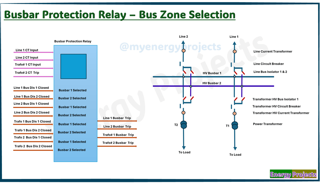
Simple represents a double busbar configuration with busbar differential protection relays. On the left-hand side, the busbar protection relay is shown, connected to current transformers (CTs) installed on each line and transformer bay.
CT Connection and Orientation
The CTs are connected with their primary direction (polarity mark) pointing towards the busbar zone.
This orientation ensures correct current direction interpretation by the differential relay.
The CT inputs to the relay are used to measure all incoming and outgoing currents for each bay, essential for differential protection operation.
Digital/Binary Inputs from Bus Isolators
Digital inputs from bus isolator (disconnector) status are wired into the relay.
These inputs indicate the connection status of each feeder to Busbar 1 or Busbar 2.
Based on these signals, the relay dynamically assigns each bay to Busbar Zone 1 or Zone 2.
Relay Zone Assignment Logic
When a Bus Isolator 1 (associated with any feeder) is closed, the relay assigns that feeder to Busbar Zone 1.
Similarly, when a Bus Isolator 2 is closed, the relay assigns that feeder to Busbar Zone 2.
This logic allows the relay to accurately track which bays are connected to which busbar, a critical function for dynamic busbar protection.
Operational Example of Busbar Zone Selection:
Busbar Zone 2 Activated:
Step 1: Line 2 Bus Disconnector 2 and Transformer 2 Bus Disconnector 2 are closed.
Step 2: The relay detects that Busbar 2 is active and considers it as Busbar Zone 2.
Step 3: The Line 2 and Transformer 2 Circuit Breakers (CBs) are closed to feed the load, charging Busbar 2, which now becomes operational and in working condition.
Busbar Zone 1 Activated:
Step 1: Line 1 Bus Disconnector 1 and Transformer 1 Bus Disconnector 1 are closed.
Step 2: The relay detects that Busbar 1 is now active and considers it as Busbar Zone 1.
Step 3: The Line 1 and Transformer 1 Circuit Breakers (CBs) are closed to feed the load, charging Busbar 1, which now becomes operational and in working condition.
Fault Simulation – Busbar Zone 1
Fault Occurs in Busbar Zone 1:
A fault is detected within Busbar Zone 1 (e.g., internal fault, short circuit).
The busbar protection relay identifies the differential current in Zone 1 exceeding the set threshold.
Based on the zone logic (from bus disconnector inputs), the relay knows Line 1 and Transformer 1 are part of Zone 1.
Relay Action:
The relay immediately trips:
Line 1 Circuit Breaker
Transformer 1 Circuit Breaker
This isolates the faulted Busbar Zone 1 and its connected feeders.
The trip is selective, affecting only Zone 1 and its associated feeders.
Post-Fault Condition:
Busbar Zone 1 is de-energized and isolated.
Busbar Zone 2 (with Line 2 and Transformer 2) continues to operate normally.
No impact on Busbar Zone 2, since the relay has correctly isolated only the faulty zone.
Fault Simulation – Busbar Zone 2
Fault Occurs in Busbar Zone 2:
A fault is detected within Busbar Zone 2 (e.g., internal short circuit).
The busbar protection relay detects an unbalanced differential current in Zone 2.
Using bus disconnector inputs, the relay identifies that Line 2 and Transformer 2 are associated with Zone 2.
Relay Action:
The relay trips:
Line 2 Circuit Breaker
Transformer 2 Circuit Breaker
This action isolates the faulted Busbar Zone 2 and its connected feeders quickly and selectively.
Post-Fault Condition:
Busbar Zone 2 is isolated and no longer operational.
Busbar Zone 1 (Line 1 and Transformer 1) remains fully functional and continues to supply load.
There is no impact on Busbar Zone 1, as the fault was confined to Zone 2.
All busbar protection relays follow the same fundamental principle of zone selection using bus disconnector status. Some time Circuit breaker status as well, which is based on specific requirements.