05.Why Distance Relay Can’t Protect 100% of line at Zone 1?
We are going discuss about distance protection in power systems protection, specifically how it functions and its limitations.
We can the reasons why distance protection has some limitations. Because of,
Fault Conditions & Errors during Faults
A fault occurs on the transmission line, and the relay detects it, but due to the fault characteristics, there may be inaccuracies in the measurements of impedance (V, I, Z). The fault may cause an imbalance between the line-to-ground or line-to-line voltages and currents.
Challenges
During faults, especially transient faults (e.g., short circuits), the system's response can be highly dynamic. Relay protection systems may not accurately determine the fault's true location due to the rapid changes in voltage and current.
Also, depending on the fault type (e.g., three-phase fault vs. single-phase fault), the impedance calculation can be skewed because the system may experience asymmetrical conditions that don’t match the assumptions in the relay algorithm.
Atmospheric and Environmental Conditions
Weather or environmental conditions can impact the accuracy of protection. For instance, high humidity or thunderstorms, including lightning strikes, can create abnormal conditions that affect relay performance.
Challenges:
Atmospheric factors like temperature, humidity, and even electromagnetic interference can cause false tripping or failure to trip. These factors can cause line impedance readings to be distorted, as the transmission line's characteristics may change.
For example, increased atmospheric moisture might reduce the insulation resistance of the line, which could lead to erratic impedance readings.
Limitations in the power system / Calculations
When the power system changes, like during load variations or changes in line configuration, the relay may struggle to accurately calculate the distance to a fault.
Challenges:
Load Changes: As the load on the system changes, the impedance can also vary, which confuses the relay.
Network Configurations: Different network setups or switching operations can alter how the relay calculates the fault distance.
Impedance Variations: The relay may not always account for changes in line impedance due to these system variations, leading to incorrect fault detection.
As the power system is dynamic during loads / Faults, Relay will not be able to get the accurate reading of
Resistance, Reactance (R , X)
Voltage , Current , Impedance(V, I, Z) .
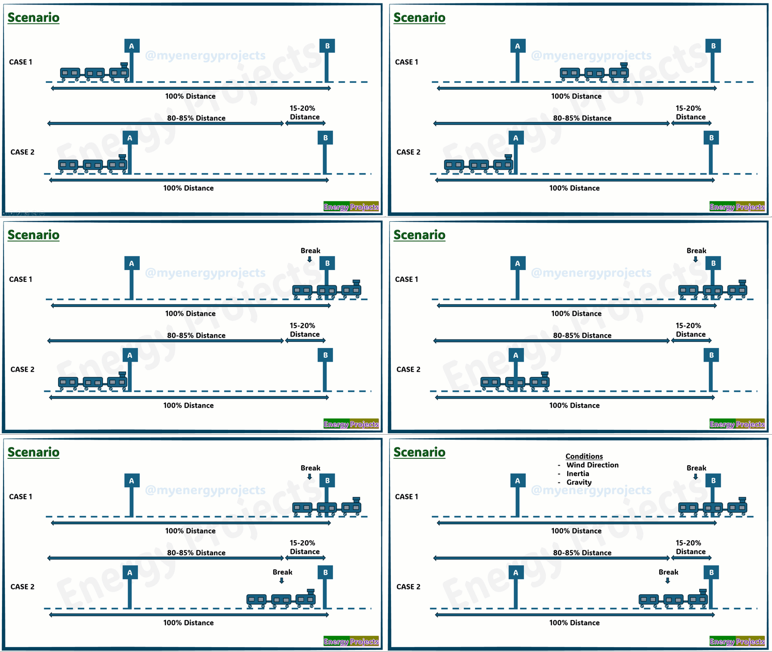

01.√3
The first reason is that calculations in any power system are never 100% accurate.
The issue lies with the square root of 3. It does not have a definite value; we can only use an approximation of 1.732. After this, we typically discard the remaining value as negligible or "garbage."
This is where the actual error begins
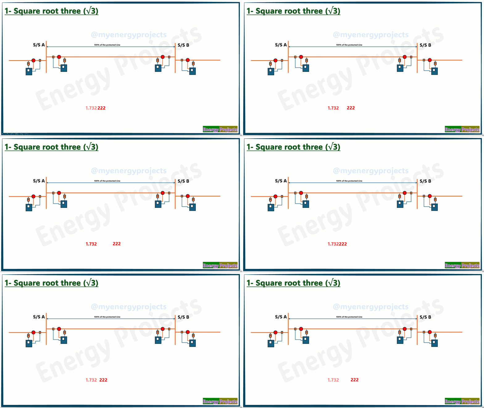

02.CT/PT Errors:
During normal operation, the measured values are almost 99% accurate. However, under fault conditions, the CT (Current Transformer) and PT (Potential Transformer) introduce errors due to saturation.
In such cases, the actual fault may occur in one zone, but the relay's discrimination zone may differ when we are protecting 100% of the line. To avoid this issue, we typically set the protection scheme to cover slightly less than 100% of the line, ensuring more accurate fault detection and preventing incorrect relay operation.


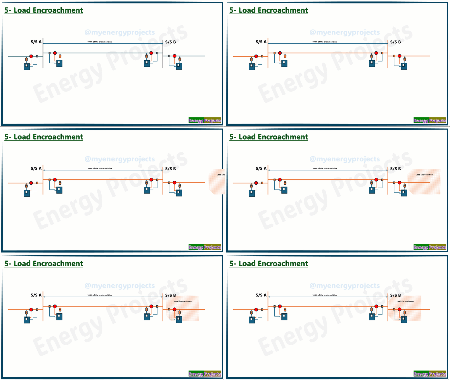
05.Load Encroachment:
During overload conditions, the impedance measured by the relay may fall within Zone 1 of the protection system. When the impedance moves closer to this zone, the relay may trip unnecessarily, even though no fault has occurred. This is particularly problematic when trying to protect 100% of the line, as the overload conditions can cause the relay to interpret the higher impedance as a fault, leading to unnecessary tripping.

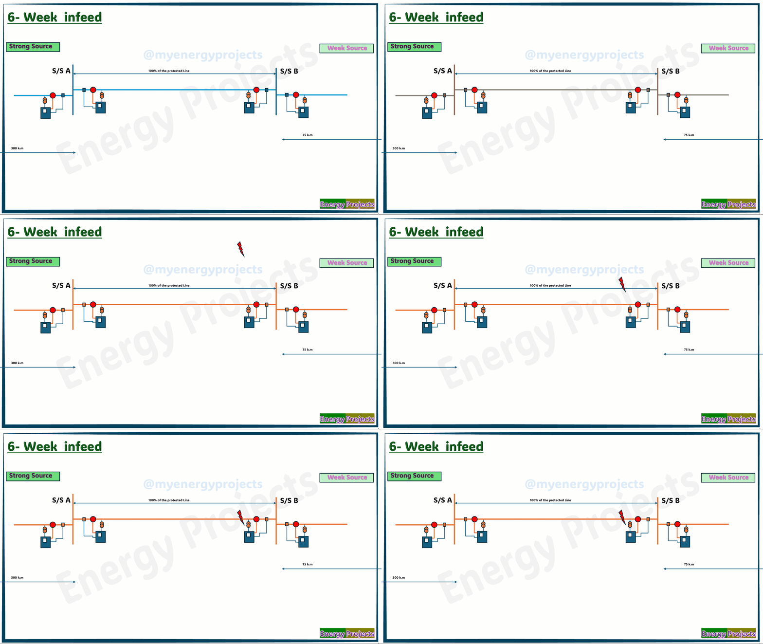
06.Weak Infeed:
When there are two different sources feeding into the grid, with the strong side having a line distance of 300 km and the weak side at 75 km, a problem arises when a fault occurs near the weak side. Due to the lower fault currents from the weak side, the relay may have difficulty identifying the exact fault location. The reduced fault current from the weak source makes it challenging for the relay to accurately determine where the fault has occurred.


Single Busbar Configuration
Single Busbar with Bus section Configuration
Single Busbar with Transfer busbar configuration
Single Busbar with Bus section + Transfer bus coupler + Section Isolator configuration
Double Busbar with Bus coupler Configuration
Double Busbar with Bus coupler + Bypass Isolator Configuration
Double Busbar with Bus coupler + Transfer Buscoupler configuration
Mesh Busbar configuration
One and Half Breaker Busbar Configuration
More
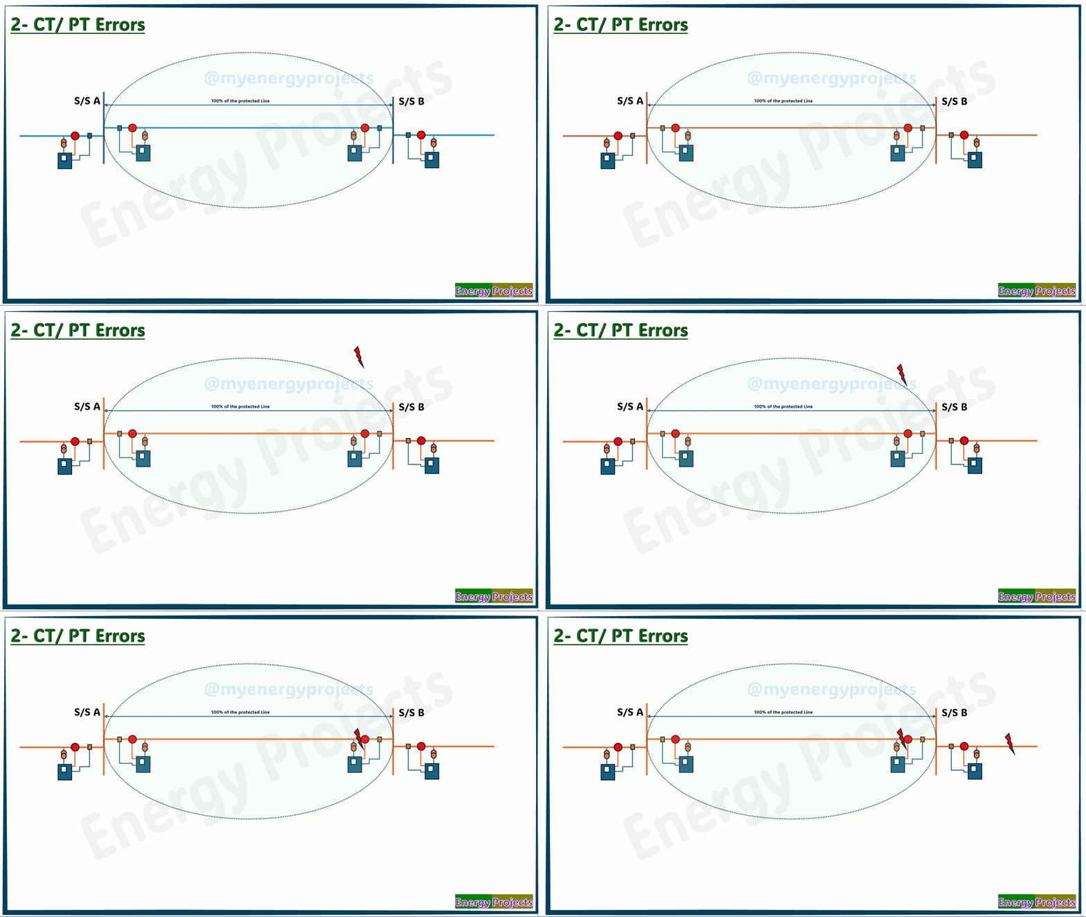
Here are the basic scenarios of Case 1 and Case 2 that would help illustrate the limitations we discussed.
Case 1:
A and B are two stations where the train must start at Station A and halt at Station B. In this case, we are running the train and applying brakes or stopping acceleration exactly near the station. However, as we can see, the train has crossed beyond the station, which is not what we require.
Case 2:
In this case, we are running the train and applying brakes or stopping acceleration after the train has travelled a certain distance, taking into account various factors. Now, the train halts exactly where needed.
In Case 2, we considered several factors such as wind direction, inertia, and gravity. We applied calculations based on these factors, which helped us stop the train precisely at Station B. These factors—wind direction, inertia, and gravity—can be seen as errors or uncertainties in the system, and to mitigate them, we applied the brakes or stopped acceleration at the right point to ensure the train halts exactly at Station B.
Similarly, in distance protection within power systems, there are certain limitations and parameters that need to be accounted for. Necessary actions are taken to handle these limitations, ensuring proper operation.
Let's go over the reasons one by one.
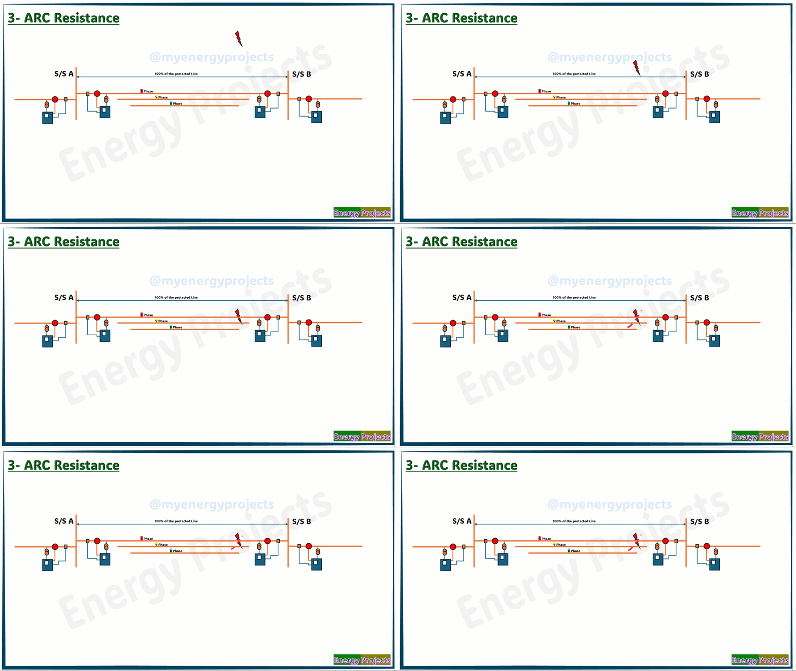
03.Arc Resistance:
When a fault occurs, an arc may form between phase-to-phase, phase-to-earth, or any other conducting objects (such as a tree or another material). The arc length and the size of the arc can vary depending on the type of fault.
The arc resistance adds to the total impedance measured by the protection system, which can result in the relay operating incorrectly or malfunctioning. This is because the additional resistance can distort the impedance calculation, leading to false tripping or delayed responses.
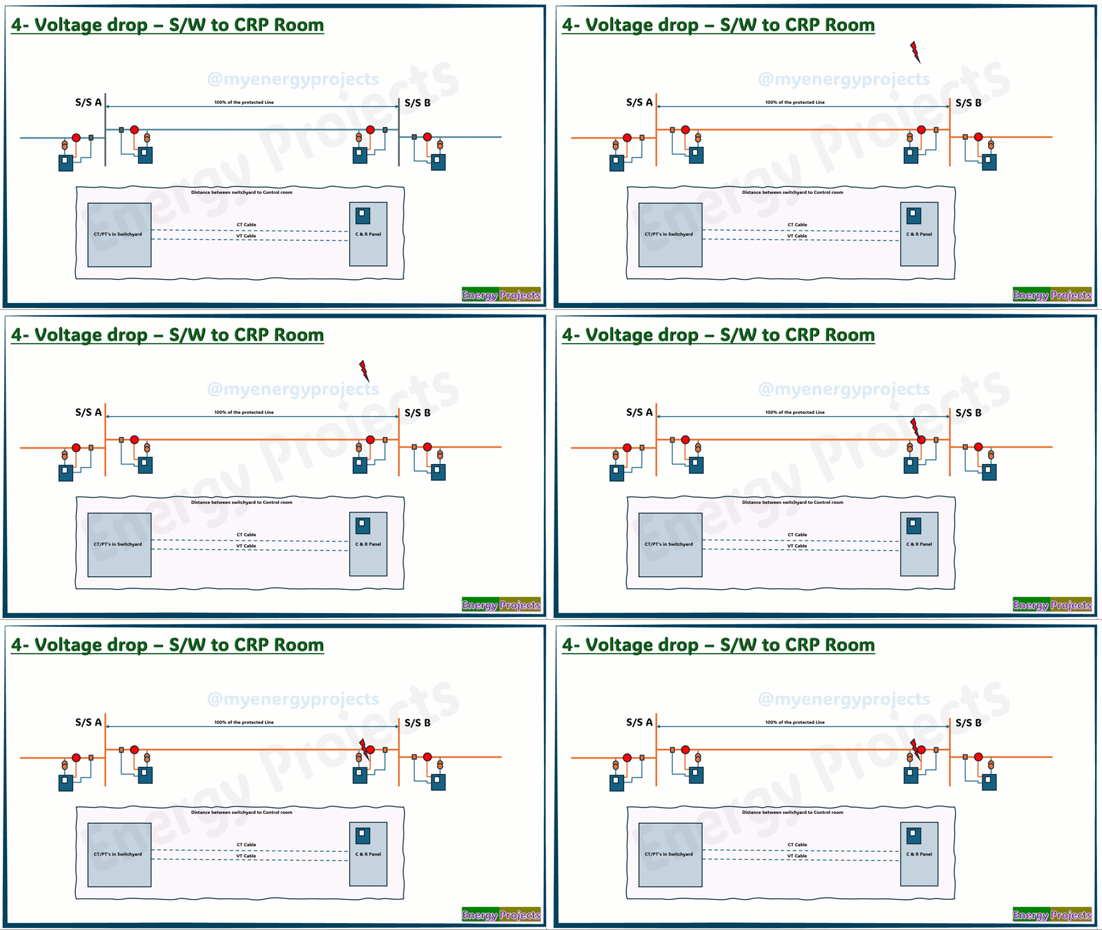
04.Voltage Drop from Switchgear to Control Room:
The voltage drop can vary depending on the size of the control cables and their length. When a fault occurs, the measurements taken by the relay may be lower due to the voltage drop between the relay and the switchgear. As a result, the measured parameters may become inaccurate, making it difficult for the relay to correctly discriminate the fault. This can lead to incorrect fault detection or improper operation of the protection system.
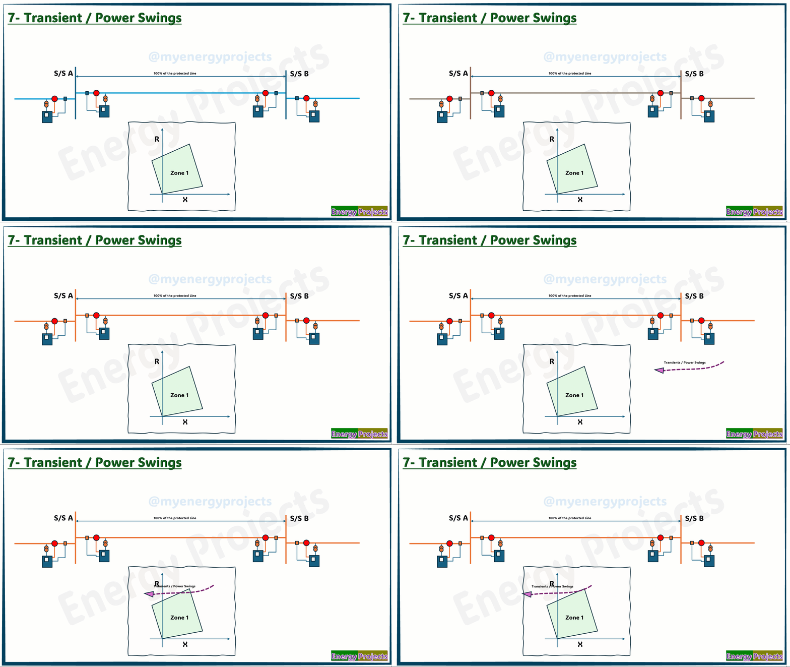
07.Transients / Power Swings:
Normally, some specific loads may draw 5 to 6 times the normal current. In other cases, when the load is suddenly thrown off, transients may occur in the grid, leading the relay to malfunction when it approaches the protected zone.

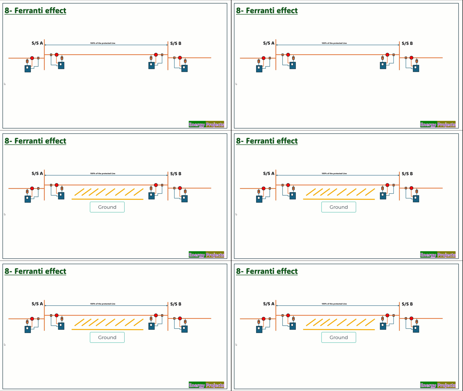
08.Ferranti Effect:
The Ferranti effect is one of the reasons where the charging currents between the conductors and from conductor to ground may lead to an increase in system voltage, causing inaccuracies in measuring fault readings.

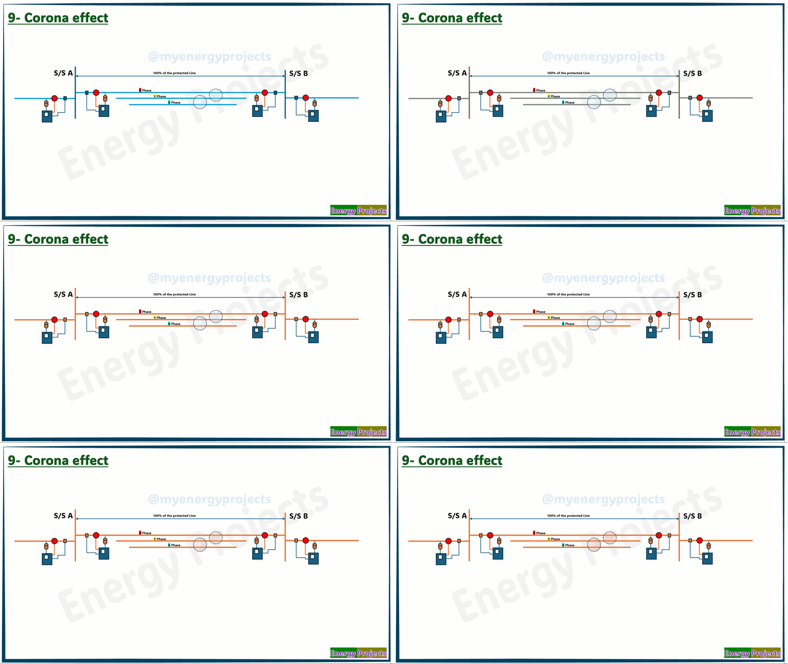
09.Corona Effect:
The corona effect occurs when high humidity around the conductor causes a breakdown, and a blue color appears over the conductor. Over time, the current flow over the conductor's surface increases, producing large fluxes around the conductor. This leads to mutual coupling between the conductors, which may result in miscalculations

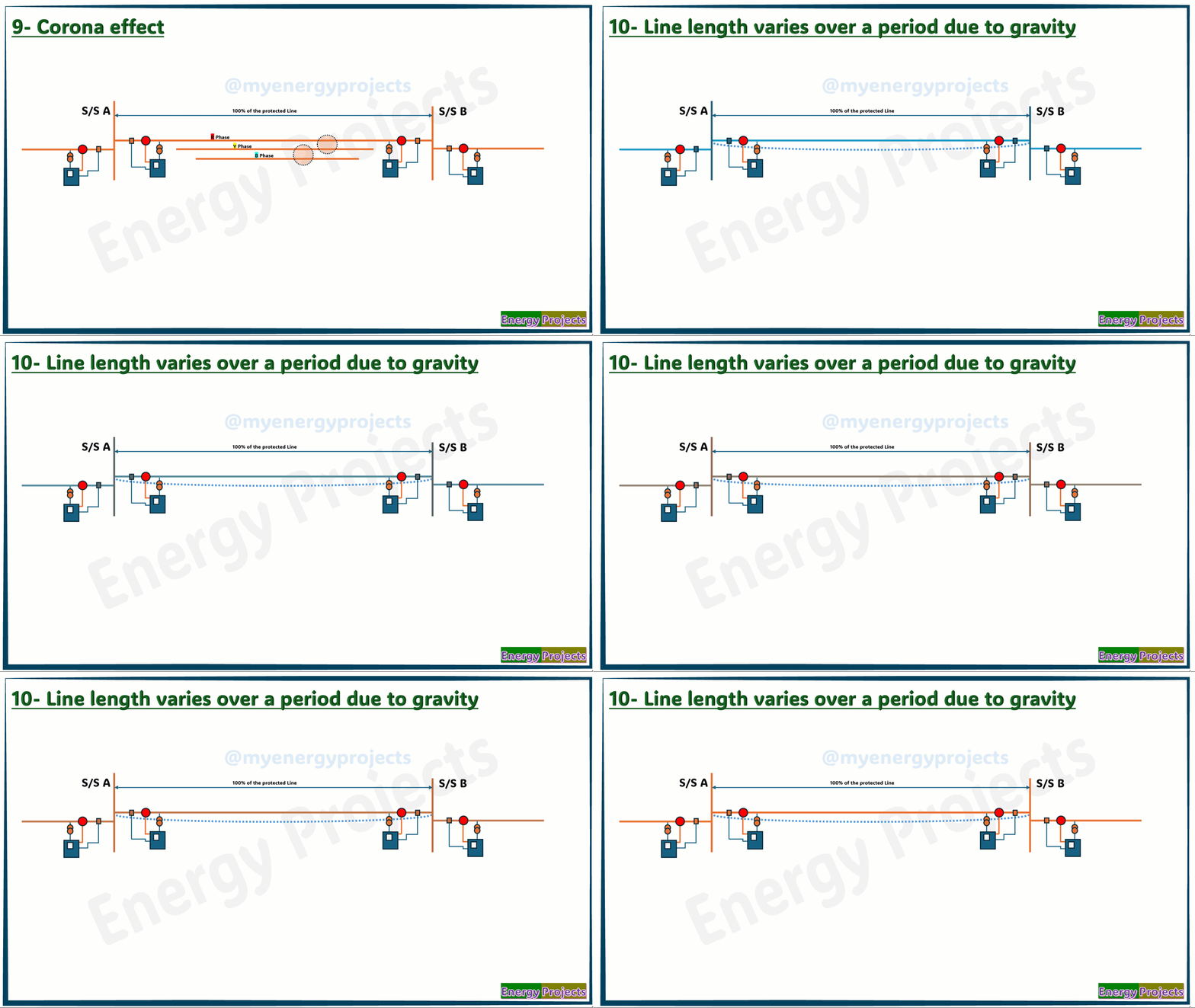
10.Line length varies over the period of time due to gravity.
Due to conductor gravity, When the conductor length changes, the cross-section of the conductor also changes, ultimately causing the resistance to vary. As a result, the measured readings and reference parameters in the relay will be different.

11.Line length varies over time due to gravity due to ice:
As the weight of the ice gravity causes it to sag, especially over long distances. This change in length leads to a variation in the conductor's cross-sectional area, resulting in a change in its resistance. Consequently, the measured readings and reference parameters in the relay will be different.
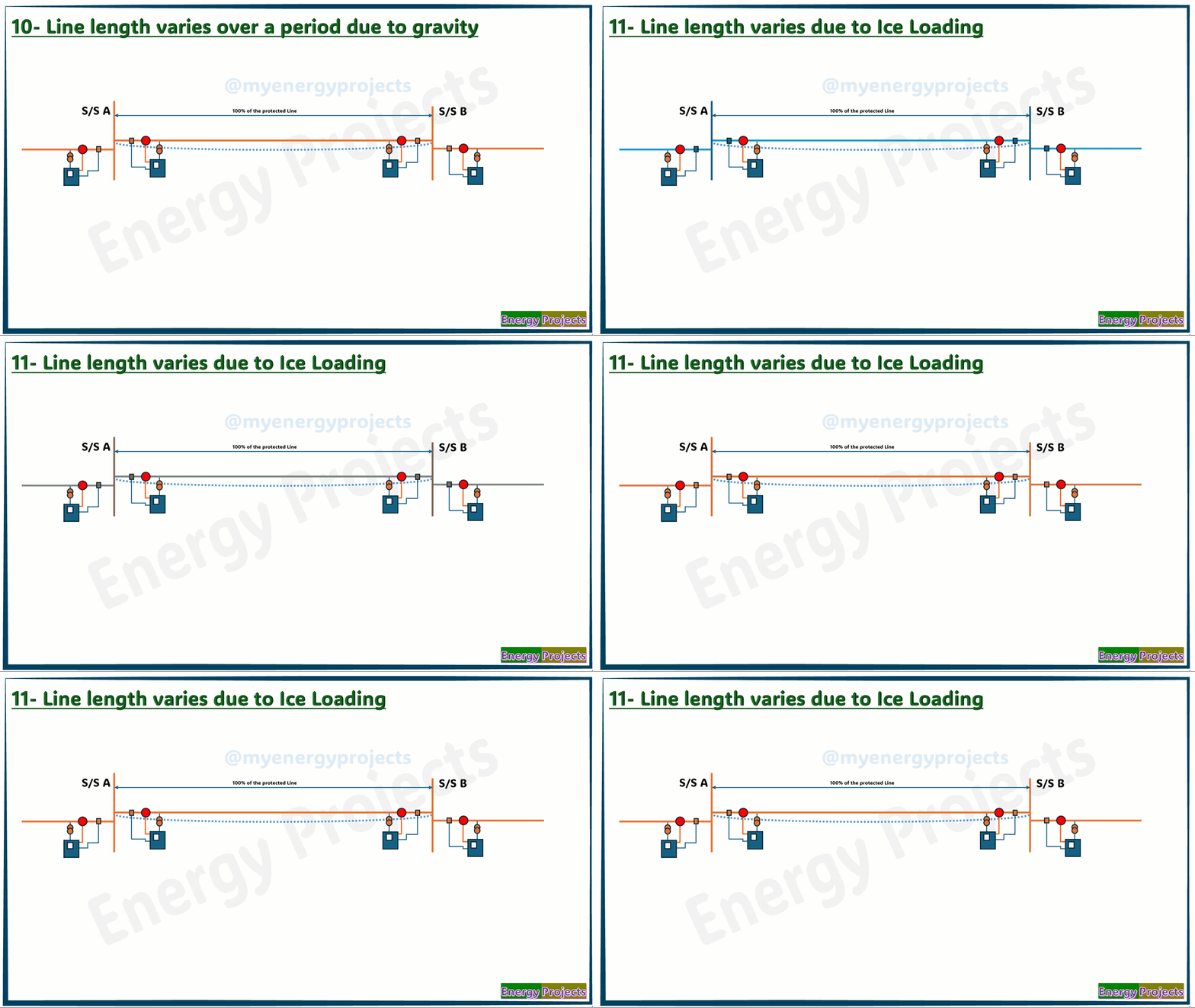

12.Inaccurate Line Length:
Typically, the CT (Current Transformer) and PT (Potential Transformer) are located at different points from the protected zone. In such cases, the line length set in the relay will usually be the average length between the CT and PT locations.
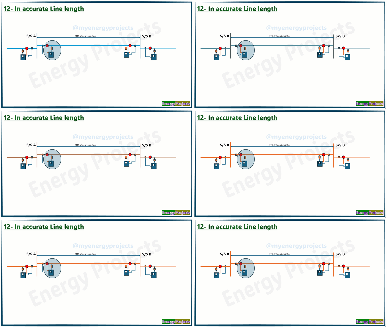

13.Induced Voltage Between Conductors:
During load conditions, parallel circuits, or other conditions, mutual coupling may form between the conductors, leading to errors in the power system parameters.
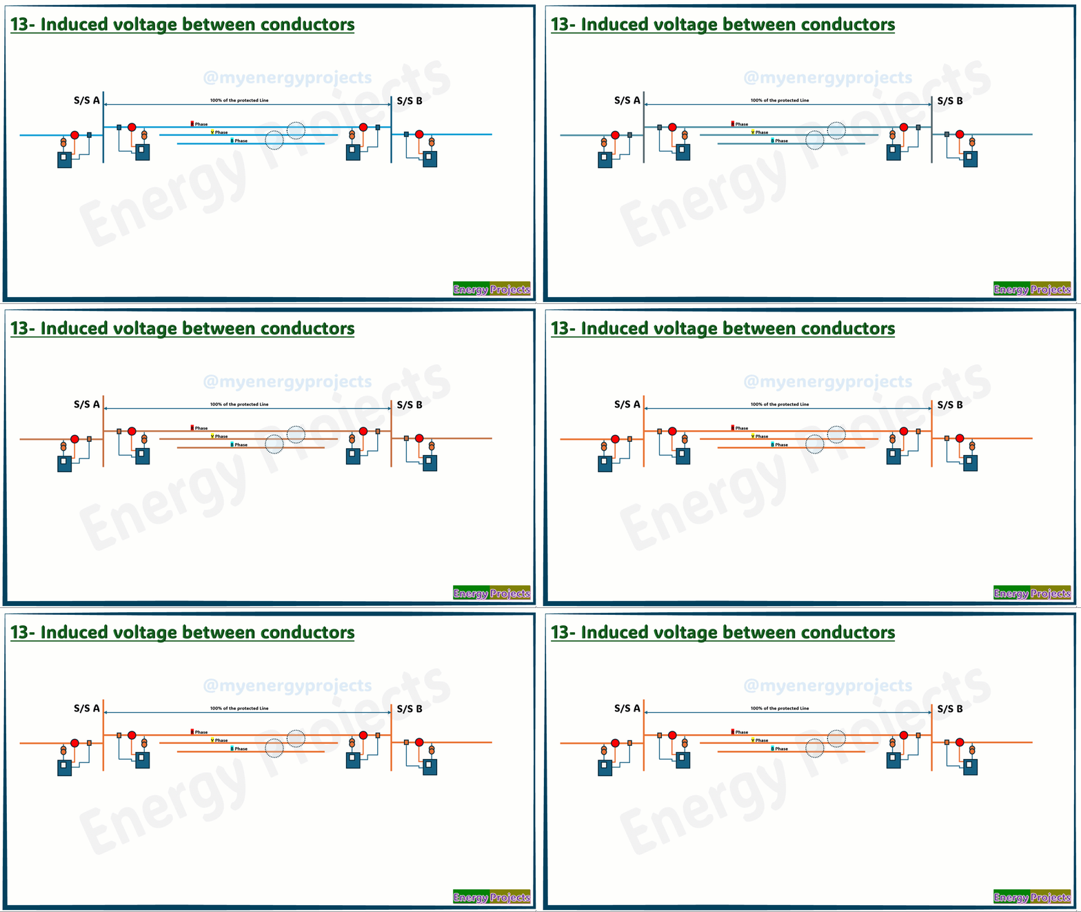

14.Line Resistance Varies Due to Temperature Coefficient:
During the daytime, due to heat, and cold during the nights, the resistance will slightly differ due to the temperature coefficient of resistance. Hence, the measured resistance in the system is inaccurate.
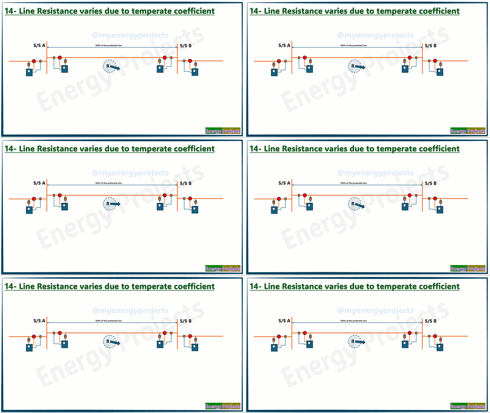

15.Leakage Current During Winter:
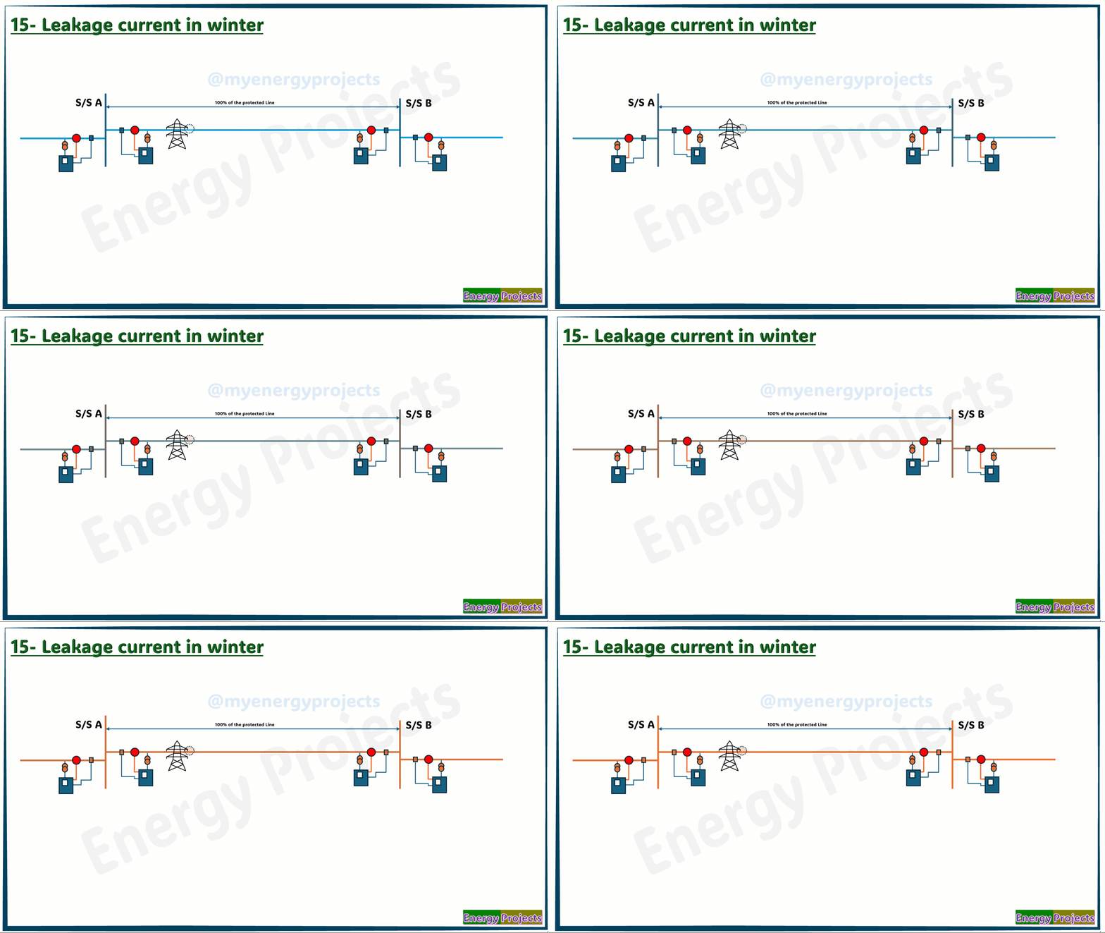
During winter, leakage currents can occur between the conductor and the tower through the insulators or any conductive air medium.

17.Leakage Current Due to Dust Deposited on the Line(OH Lines only):
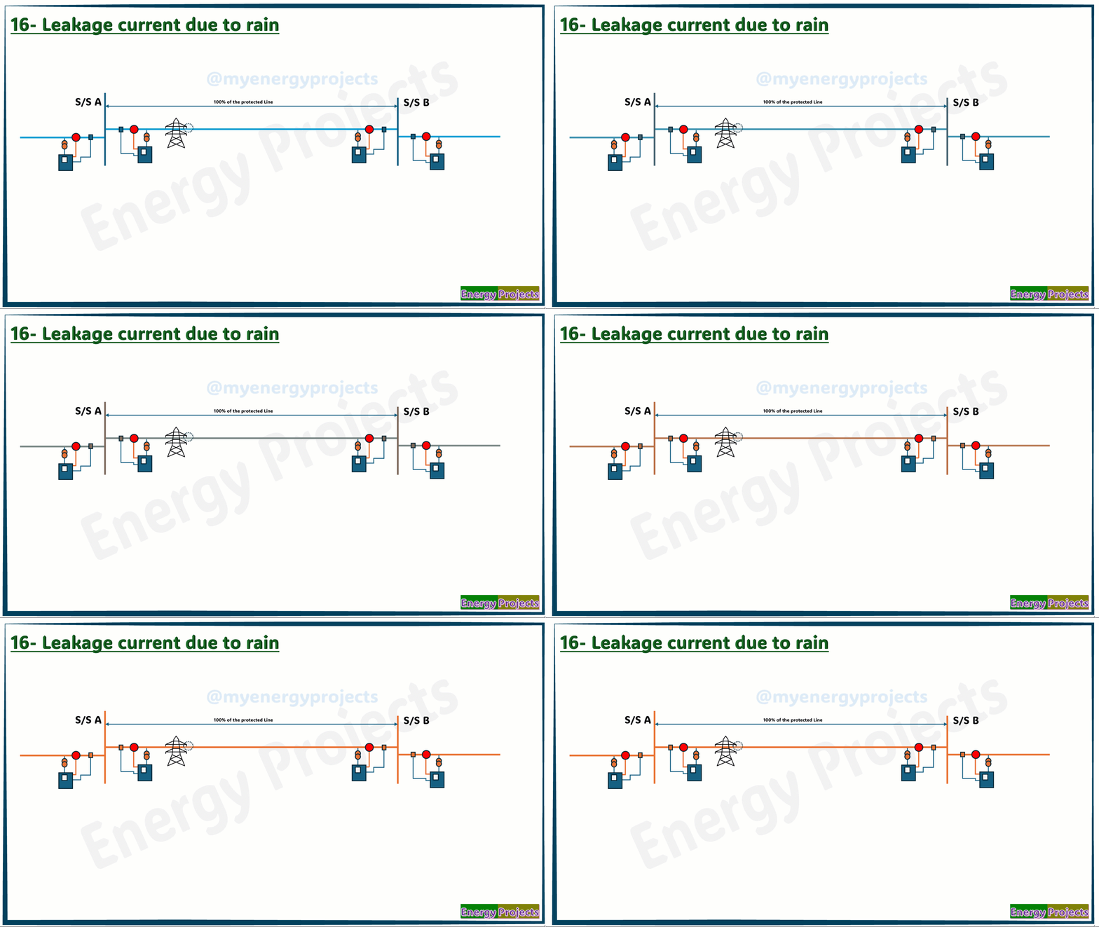
Due to the dust deposited on the insulators, leakage currents can occur between the conductor and the tower through the insulators. The magnitude of the leakage current depends on the thickness of the dust layer.

18.Man-Made Mistakes:
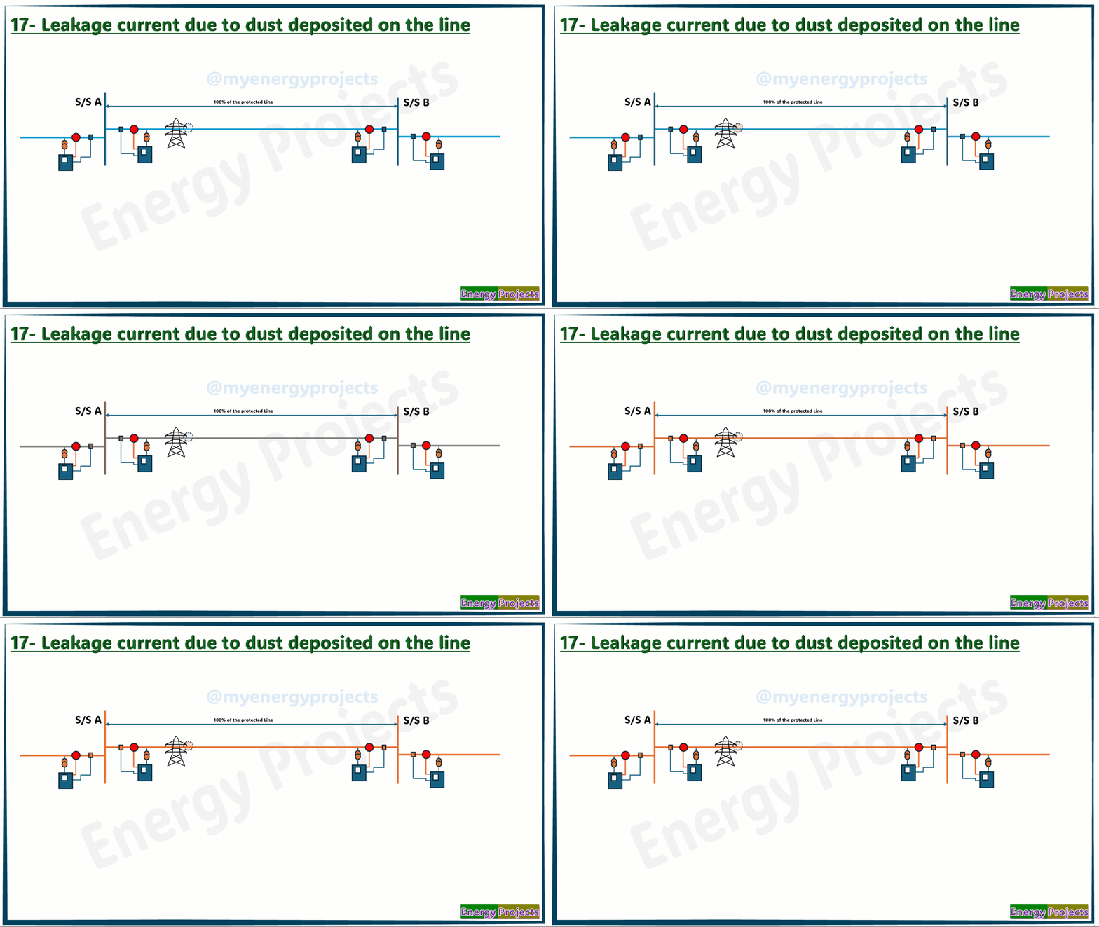
Another possible reason could be man-made mistakes, which can lead to maloperation.

16.Leakage Current During Rain:
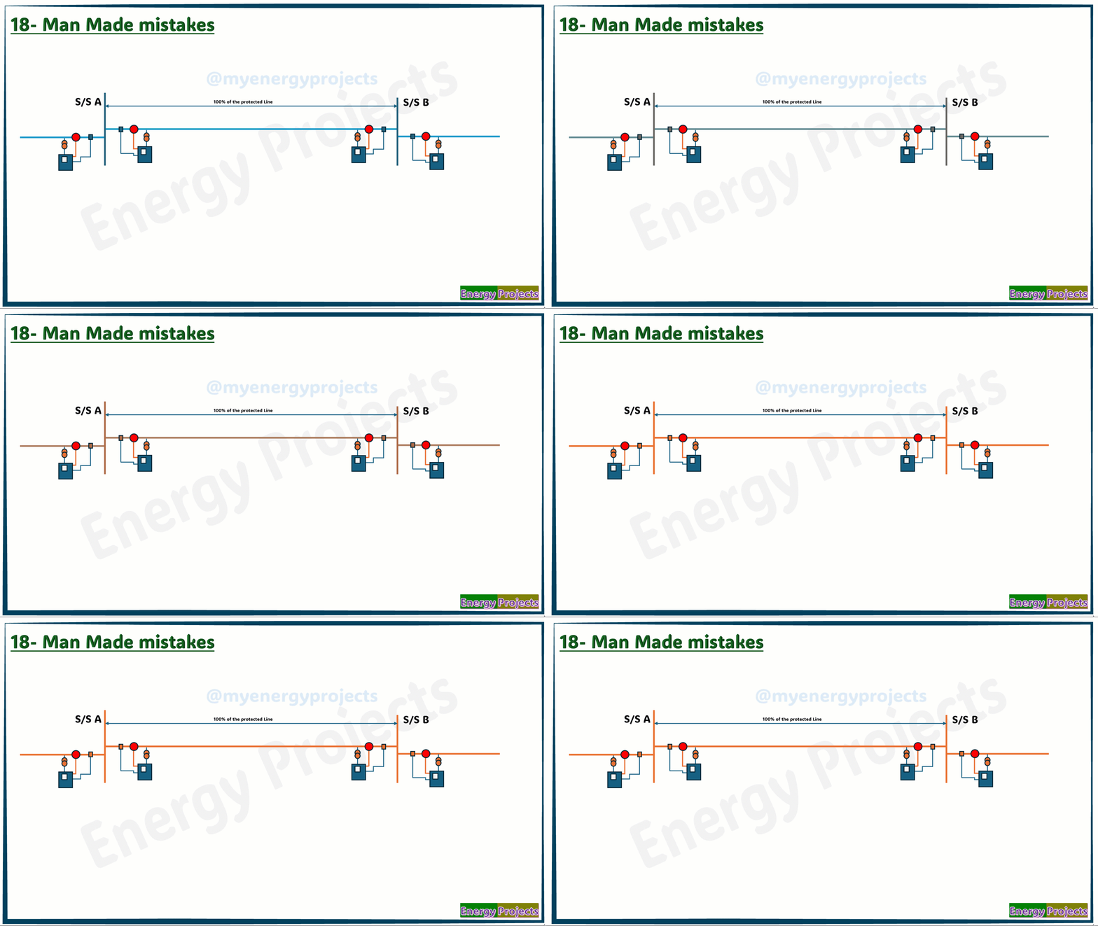
During rain, leakage currents can occur between the conductor and the tower through the insulators or any conductive air medium

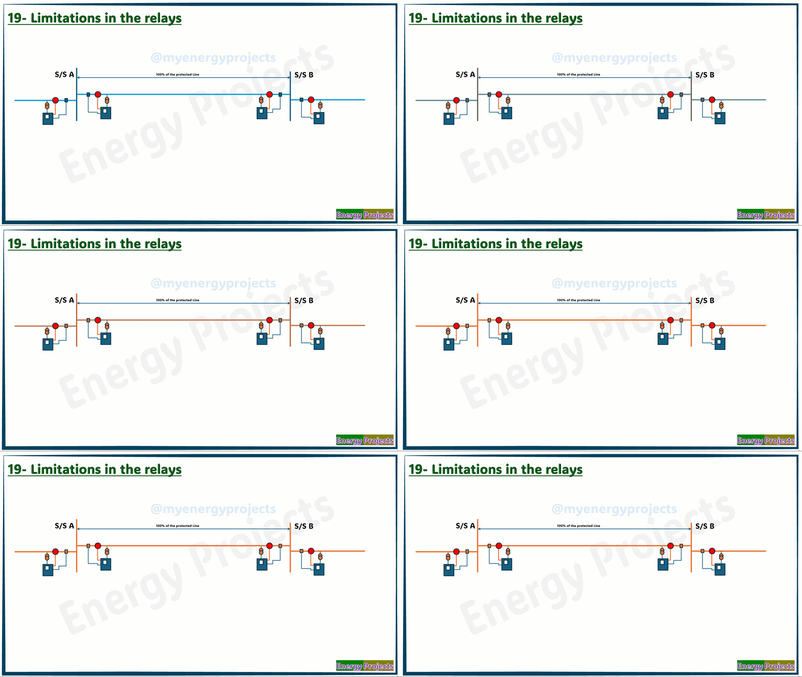
19- Limitations in the relays
Due to limitations in the relays, each manufacturer uses different algorithms to identify faults. For example, if we place 10 different makes of distance protection relays at the same point to test, each relay will respond differently to the same fault simulation.
