13.Methods to achieve an effective star point
Importance of CT Star Point
Correct Polarity and Direction of Current Flow
The CT star point ensures that all CTs are aligned with the system's current flow.
Incorrect star point placement can lead to protection relay malfunction (e.g., relay trips during normal load or fails during faults).
Relay Reference Point
The star point is often the reference point for protection relays (like differential or earth fault relays).
If placed incorrectly, the relay will "see" the wrong differential or residual current.
Earth Fault Protection
For residual current measurement (e.g., neutral overcurrent or restricted earth fault protection), CTs must be connected properly with the star point aligned away from the protected equipment.
If CTs are star-pointed on the wrong side, it can cause false trips or no trip during actual faults.


Single Busbar Configuration
Single Busbar with Bus section Configuration
Single Busbar with Transfer busbar configuration
Single Busbar with Bus section + Transfer bus coupler + Section Isolator configuration
Double Busbar with Bus coupler Configuration
Double Busbar with Bus coupler + Bypass Isolator Configuration
Double Busbar with Bus coupler + Transfer Buscoupler configuration
Mesh Busbar configuration
One and Half Breaker Busbar Configuration
More
Method 1
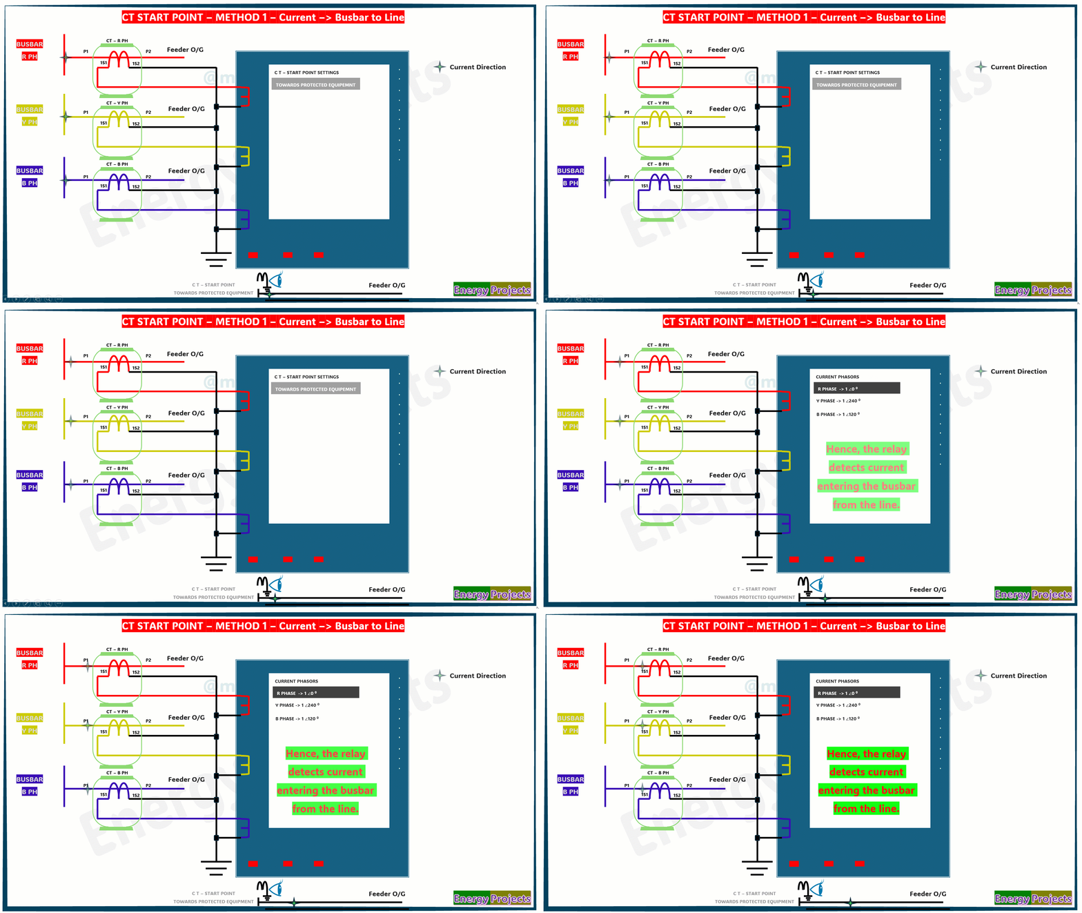
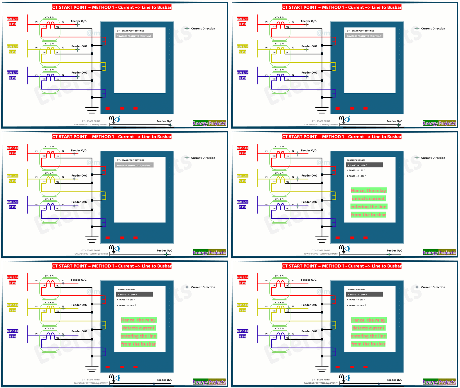
In this method, we connect the P1 terminal of each current transformer (CT) towards the busbar, and the P2 terminal towards the protection equipment. This orientation ensures that the CTs correctly sense current flowing from the busbar to the line.
The star point is created by shorting the S2 terminals (secondary) of all three CTs—R phase (S2), Y phase (S2), and B phase (S2). These S2 terminals are then grounded to form the common reference point (star point). The S1 terminals from each CT are connected to the respective phase current inputs of the protection relay (R, Y, and B inputs).
In this configuration, we also define in the numerical relay settings that the CT star point is on the side of the protected equipment. This virtual setting in the relay must align with the physical wiring to ensure proper vector relationships.
By maintaining both the physical and logical (relay setting) orientation correctly, the relay can accurately identify the direction of current flow, whether it's:
From busbar to line, or
From line to busbar.
This correct identification is crucial for directional protection functions such as:
Directional overcurrent protection
Reverse power protection
Differential protection schemes
Methods to achieve an effective star point
Using the Physical Star Point at the Secondary Terminals of CT Cores
The star point can be formed by connecting the secondary terminals (typically S2) of current transformers (CTs) together.
Reversing the Polarity of CT Terminals (Swapping P1 & P2)
In cases where CT connections are incorrect, the effective star point can be corrected by swapping the primary terminals (P1 and P2) to restore the correct current direction.
Virtual Star Point Configuration in Modern Numerical Relays
In advanced numerical relays, the star point can be configured virtually within the relay settings, independent of the physical CT wiring. This allows flexibility in correcting phase or polarity issues without rewiring.


